00195741-0102_UM_D1_D2_SR605_EN.pdf - 第125页
User Manual SIPLACE D1/D2 3 Technical data for the machine From software version SR.605.xx 07/2008 EN Edition 3.7 Gantry system 125 The Y axis essentially consists of the following main modules: – Y axis linear drive wit…
3 Technical data for the machine User Manual SIPLACE D1/D2
3.7 Gantry system From software version SR.605.xx 07/2008 EN Edition
124
3.7.3 Technical data for the X axis
3
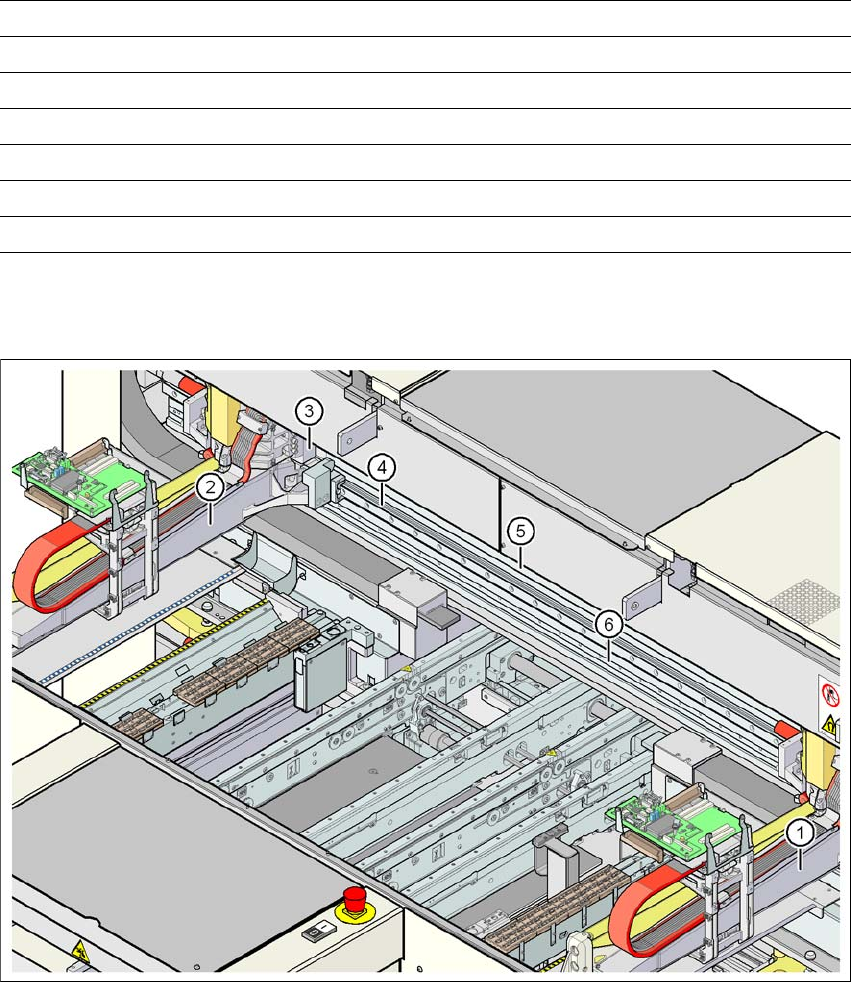
3.7.4 Structure of the Y axis
3
Fig. 3.7 - 3 Structure of the Y axis on the example of the D2 machine
Drive Three-phase AC servomotor/toothed belt
Maximum speed 2.5 m/s
Traversing path 470 mm
Distance measuring system Metal linear scale
Measuring length 520 mm
Scale length 520 mm
Resolution 1 μm
(1) Gantry 1 (SIPLACE D1/D2) (4) Guide system
(2) Gantry 2 (SIPLACE D2) (5) Permanent magnet
(3) Adapter plate (6) Measuring system

User Manual SIPLACE D1/D2 3 Technical data for the machine
From software version SR.605.xx 07/2008 EN Edition 3.7 Gantry system
125
The Y axis essentially consists of the following main modules:
– Y axis linear drive with permanent magnet (item 5 in Fig. 3.7 - 3
, page 124) and adapter
plate (item 3 in Fig. 3.7 - 3
, page 124)
– Y axis guide system (item 4 in Fig. 3.7 - 3
, page 124)
– Y axis measuring system (item 6 in Fig. 3.7 - 3
, page 124)
The Y axis is driven by a linear motor. The secondary part of the drive is made up of permanent
magnets and is mounted on the machine frame. The primary part is bolted to the gantry (adapter
plate). An anti-crash circuit prevents the traversing paths of the gantries meeting.
3.7.5 Technical data for the Y axis
Drive Direct, linear motor
Speed max. 2.5 m/s
Traversing path of the gantry, SIPLACE D1
Gantry 1: from the middle of the machine to location 1
Gantry 1: from the middle of the machine to location 2
+ 778 mm
- 801 mm
Traversing path of the gantry, SIPLACE D2
Gantry 1: from the middle of the machine to location 1
Gantry 2: from the middle of the machine to location 2
+ 795 mm
+ 677 mm
Distance measuring system Metal linear scale
Scale length 1950 mm
Resolution 1 μm
3 Technical data for the machine User Manual SIPLACE D1/D2
3.8 PCB conveyor system From software version SR.605.xx 07/2008 EN Edition
126
3.8 PCB conveyor system
The machine is supplied with a PCB single conveyor as standard. The PCB dual conveyor is avail-
able as an option from the factory (see Section 3.8.7
, page 134). The left or the right side of the
PCB conveyor can be used as the stationary side, as required.
The conveyor belts are driven by DC motors. The lifting table for clamping the PCBs is located in
the processing area. The PCB conveyor width can either be set from the user interface or preset
in the placement program.
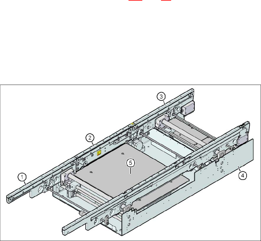
3.8.1 Structure
3.8.1.1 Structure of the PCB single conveyor
3
Fig. 3.8 - 1 Structure of the PCB single conveyor
(1) Input conveyor
(2) Processing conveyor
(3) Output conveyor
(4) Assembly tray
(5) Lifting table