00195741-0102_UM_D1_D2_SR605_EN.pdf - 第119页
User Manual SIPLACE D1/D2 3 Technical data for the machine From software version SR.605.xx 07/2008 EN Edition 3.6 Placement head 119 3.6.3 SIPLACE Pick&Place head for high-precision IC placement Item no. 001 19833-xx…

3 Technical data for the machine User Manual SIPLACE D1/D2
3.6 Placement head From software version SR.605.xx 07/2008 EN Edition
118
Component specification
Max. height
Min. lead pitch
Min. lead width
Min. ball pitch
Min. ball diameter
Min. dimensions
Max. dimensions
Max. weight
8.5 mm
0.3 mm
0.15 mm
0.25 mm for components< 18 x 18 mm²
0.35 mm for components ≥18 x 18 mm²
0.14 mm for components < 18 x 18 mm²
0.2 mm for components ≥ 18 x 18 mm²
0.6 x 0.3 mm²
27 x 27 mm²
5 g
Programmed power stage
1
2
3
4
5
Programmed set-down force [N]
2.4 ± 0.5
2.4 ± 0.5
3 + 1
4 + 1
5 + 1
Nozzle types 8xx, 9xx
X/Y accuracy
b
± 52.5 μm/3σ, ± 70 μm/4σ
Angular accuracy ± 0.225°/3σ, ± 0.3°/4σ
Component range 99.8%
Component camera type 29
Illumination levels 5
Possible illumination level setting
256
5
a) Please note that the component range that can be placed is also affected by the pad geometry, the cus-
tomer-specific standards and the packaging tolerances.
b) The accuracy value was measured using the vendor-neutral IPC standard
User Manual SIPLACE D1/D2 3 Technical data for the machine
From software version SR.605.xx 07/2008 EN Edition 3.6 Placement head
119
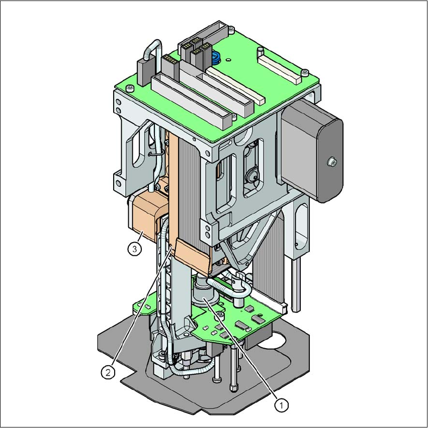
3.6.3 SIPLACE Pick&Place head for high-precision IC placement
Item no. 00119833-xx SIPLACE Pick&Place head, D-series
3
Fig. 3.6 - 5 Pick&Place head for high-precision IC placement
(1) DP axis
(2) Z axis drive
(3) Incremental distance measuring system for the Z axis
3.6.3.1 Description
This highly sophisticated placement head works on the Pick&Place principle. The SIPLACE
Pick&Place head is suitable for processing particularly difficult or large components. The compo-
3 Technical data for the machine User Manual SIPLACE D1/D2
3.6 Placement head From software version SR.605.xx 07/2008 EN Edition
120
nents are picked up by the placement head, optically centered on the way to the placement posi-
tion and rotated into the necessary placement angle. They are then placed gently and accurately
onto the PCB with a controlled blast of air.
The standard nozzles for the Pick&Place head are the type 5xx nozzles. It is also possible to fit
an adapter and then use type 4xx nozzles and type 8xx and 9xx nozzles for the Collect&Place
heads.
3.6.3.2 Technical data
3
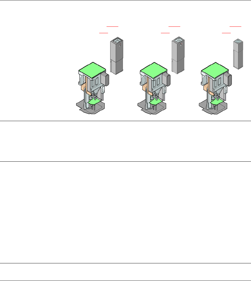
Pick&Place head
Fine-pitch camera
CO camera type 36
(see Section 3.9.3
,
page 140
)
Pick&Place head
Fine-pitch camera
CO camera type 33
(see Section 6.3.2
,
page 287
)
Pick&Place head
Flip-chip camera
CO camera type 25
(see Section 6.3.1
,
page 285
)
Range of components
a
0603 to SO, PLCC,
QFP, BGA, special
components, bare dies,
flip-chips
0402 to SO, PLCC,
QFP, BGA, special
components, bare dies,
flip-chips
0201 to SO, PLCC,
QFP, sockets, plugs,
BGA, special compo-
nents, bare dies, flip-
chips, shields
Component specification
Max. height
Min. lead pitch
Min. lead width
Min. ball pitch
Min. ball diameter
Min. dimensions
Max. dimensions
Max. weight
b
19 mm
0.4 mm
0.24 mm
0.56 mm
0.32 mm
1.6 x 0.8 mm²
32 x 32 mm²
(single measurement)
85 x 85 mm² or
max. 200 x 125 mm²
(with restrictions)
100 g
19 mm
0.3 mm
0.15 mm
0.35 mm
0.2 mm
1.0 x 0.5 mm²
55 x 45 mm²
(single measurement)
85 x 85 mm² or
max. 200 x 125 mm²
(with restrictions)
100 g
19 mm
0.25 mm
0.1 mm
0.14 mm
0.08 mm
0.6 x 0.3 mm²
16 x 16 mm²
(single measurement)
100 g
Programmable set-down
force 1.0 N - 15 N 1.0 N - 15 N 1.0 N - 15 N