00195741-0102_UM_D1_D2_SR605_EN.pdf - 第167页
User Manual SIPLACE D1/D2 3 Technical data for the machine From software version SR.605.xx 07/2008 EN Edition 3.10 Feeder modules 167 PLEASE NOTE – The waffle- pack tray holder ca n only be set up at location 1. – The fe…
3 Technical data for the machine User Manual SIPLACE D1/D2
3.10 Feeder modules From software version SR.605.xx 07/2008 EN Edition
166
3.10.9.3 Assembly
3
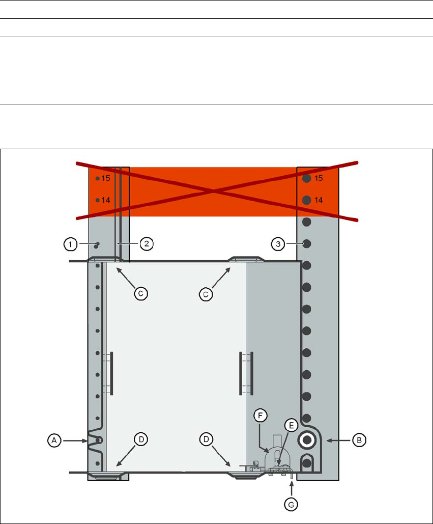
Fig. 3.10 - 18 Installation
(1) Centering pins
(2) Magnetic rail
(3) Centering ball
(14), (15) This position must not be filled.
Positioning options Location 1 (SIPLACE D1)
Range of placement heads P&P, C&P6, C&P12
Max. waffle-pack tray height
including components
C&P12
C&P6
P&P
12.5 mm
12.5 mm
28.5 mm

User Manual SIPLACE D1/D2 3 Technical data for the machine
From software version SR.605.xx 07/2008 EN Edition 3.10 Feeder modules
167
PLEASE NOTE
– The waffle-pack tray holder can only be set up at location 1.
– The feeder module positions 14 and 15 on the component table must not be filled.
– The component trolley cannot be docked in/out while the holder is fitted.
→ Insert the front side of the waffle-pack tray holder into the associated centering pin (A in Fig.
3.10 - 18
, page 166).
→ Then position the hole on the rear side of the waffle-pack tray holder onto the centering ball
on the component table (B in Fig. 3.10 - 18
, page 166).
→ Check that the waffle-pack tray holder is firmly seated on the component table.
→ Position one side of the waffle-pack tray carrier in the mounting (C in Fig. 3.10 - 18
, page 166).
Then press the other side into the mounting (D in Fig. 3.10 - 18
, page 166).
→ Slide the waffle-pack tray up against the stop (E in Fig. 3.10 - 18
, page 166).
→ Secure the waffle-pack tray carrier by pressing the thrust pad (F in Fig. 3.10 - 18
, page 166)
downwards.
→ To remove the waffle-pack tray carrier, press the thrust pad once more.
PLEASE NOTE
Using the holder for small waffle-pack trays (136 mm) a waffle-pack tray (JEDEC or CENELEC
waffle-pack tray) can be fitted directly to the holder, in other words, without a waffle-pack tray car-
rier being used. However, the retainer will require changing (G in Fig. 3.10 - 18, page 166).
WARNING
All locations must be equipped with feeder modules in order to guarantee operational reliability.
If there are not enough feeder modules available, unassigned locations should be fitted with a
hand guard (dummy feeder module). When a waffle-pack tray holder is set up, the remaining
locations have to be protected again with a hand guard.
3.10.9.4 Changing the retainer
→ Hold the retainer (G in Fig. 3.10 - 18, page 166) firmly. Press the thrust pad downwards (F in
Fig. 3.10 - 18
, page 166) and remove the retainer by pressing it out sideways.
3 Technical data for the machine User Manual SIPLACE D1/D2
3.10 Feeder modules From software version SR.605.xx 07/2008 EN Edition
168
3.10.9.5 Data entry
Define the waffle-pack trays as described in the SIPLACE Pro operating instructions.
3.10.10 Dip module
Item no. 00117010-xx Dip module for flux and adhesives
3
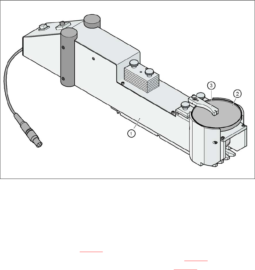
Fig. 3.10 - 19 Dip module
(1) Dip module
(2) Rotating plate
(3) Squeegee
3.10.10.1 Description
The dip module (item 1 in Fig. 3.10 - 19) is used to wet flip-chip and CSP components with flux or
conductive adhesive. The flux holder is a rotating plate (item 2 in Fig. 3.10 - 19
), on which a thin
film of flux (e.g. 40 μm) is created with a squeegee (item 3 in Fig. 3.10 - 19
). This method is par-
ticularly suitable for highly viscous (honey-like) fluxes. The amount of flux required for the process
is reduced to a minimum coating thickness since only the undersides of the bumps have to be wet-
ted.