00195741-0102_UM_D1_D2_SR605_EN.pdf - 第285页
User Manual SIPLACE D1/D2 6 Station extensions From software version SR.605.xx 07/2008 EN Edition 6.3 Component camera for the Pick&Place head 285 6.3 Component camera for the Pick&Place head 6.3.1 St ationary P&…

6 Station extensions User Manual SIPLACE D1/D2
6.2 Waffle-pack changer (WPC) From software version SR.605.xx 07/2008 EN Edition
284
6.2.6.1 Safety equipment
EMERGENCY STOP button
When you press the emergency stop button, the entire system, i.e. the SIPLACE D1 and waffle-
pack changer, are stopped immediately. When the emergency stop button is released, the entire
system is started by pressing the start button on the D1 machine. Placement can then be contin-
ued or canceled.
PLEASE NOTE
Look out for any incompletely placed PCBs.
Safety door
When the safety doors are opened, the lifting axis and the feed axis of the waffle-pack changer
are stopped. The waffle-pack changer resumes its sequence of functions when the safety doors
are closed.
CAUTION 6
Do not open the safety doors of the waffle-pack changer while a component is being picked up
from the waffle-pack changer. 6
6.2.6.2 Operation, preventive maintenance, service
Detailed documentation of the operation, preventive maintenance and servicing of the waffle-pack
changer can be found in the manuals supplied with the waffle-pack changer.
User Manual SIPLACE D1/D2 6 Station extensions
From software version SR.605.xx 07/2008 EN Edition 6.3 Component camera for the Pick&Place head
285
6.3 Component camera for the Pick&Place head
6.3.1 Stationary P&P component camera (type 25) 16 x 16, digital (FC camera)
Item no. 00119718-xx Component camera, stationary, 16x16, digital, type 25
6
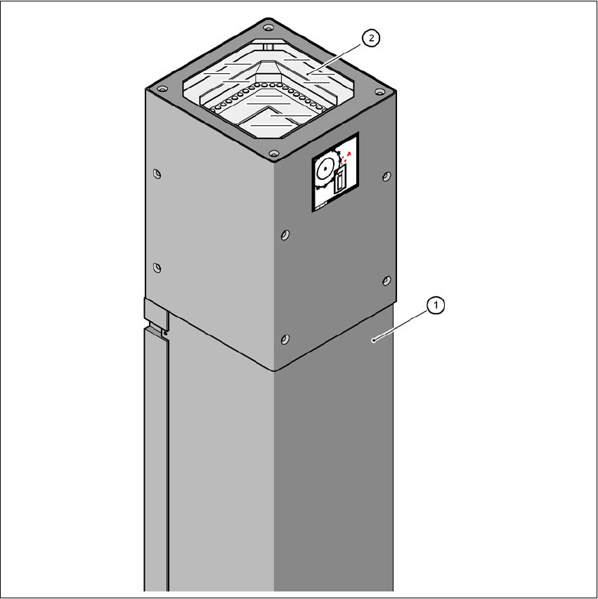
Fig. 6.3 - 1 Stationary P&P component camera (type 25) 16 x 16, digital (FC camera)
(1) Camera housing with integral camera and camera amplifier
(2) Glass plate - over the illumination and lens levels
6
6 Station extensions User Manual SIPLACE D1/D2
6.3 Component camera for the Pick&Place head From software version SR.605.xx 07/2008 EN Edition
286
6.3.1.1 Position of the component cameras for the Pick&Place head on the D1 machine
6
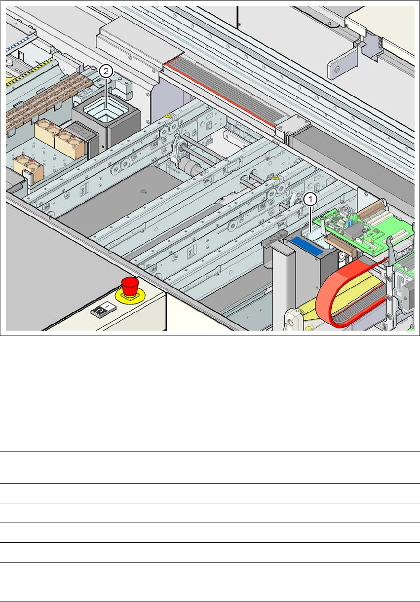
Fig. 6.3 - 2 Position of the component camera for the Pick&Place head on the D1 machine
(1) Assembly position for the stationary CO camera, P&P, type 36 (32 x 32) or type 33 (55 x 45)
(2) Assembly position for the stationary CO camera, P&P, type 25 (16 x 16)
6.3.1.2 Technical data, component camera, stationary, P&P, type 25
6
Component dimensions 0.2 x 0.2 mm² up to 16 x 16 mm² for single component measurement
Range of components 0201 to SO, PLCC, QFP, sockets, plugs, BGA, special components,
bare dies, flip-chips, shields
Min. lead pitch 0.25 mm
Min. lead width 0.1 mm
Min. ball pitch 0.14 mm
Min. ball diameter 0.08 mm
Field of vision 19.4 x 19.4 mm²
Method of illumination Front-illumination (6 levels, programmable as required)