00195741-0102_UM_D1_D2_SR605_EN.pdf - 第112页
3 Technical data for the machine User Manual SIPLACE D1/D2 3.6 Placement head From software version SR.605.xx 07/2008 EN Edition 112 3 Fig. 3.6 - 2 12-segment Collect&Place head - F unction groups, part 2 3 (1) Inter…
User Manual SIPLACE D1/D2 3 Technical data for the machine
From software version SR.605.xx 07/2008 EN Edition 3.6 Placement head
111
3.6 Placement head
3.6.1 12-segment Collect&Place head for high-speed placement
Item no. 00119876-xx, SIPLACE 12 C&P head, D-series
3
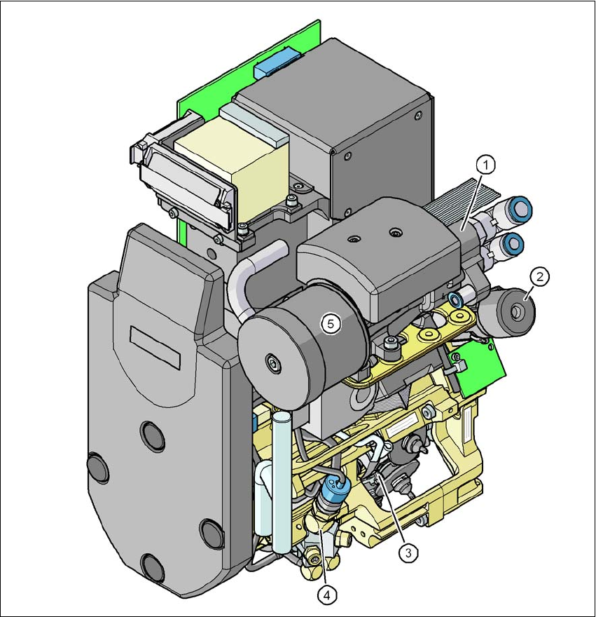
Fig. 3.6 - 1 12-segment Collect&Place head - Function groups, part 1
3
(1) Vacuum generator
(2) Turning station, DP axis
(3) Star with 12 sleeves, star axis
(4) Forced air valve
(5) Silencer
3 Technical data for the machine User Manual SIPLACE D1/D2
3.6 Placement head From software version SR.605.xx 07/2008 EN Edition
112
3
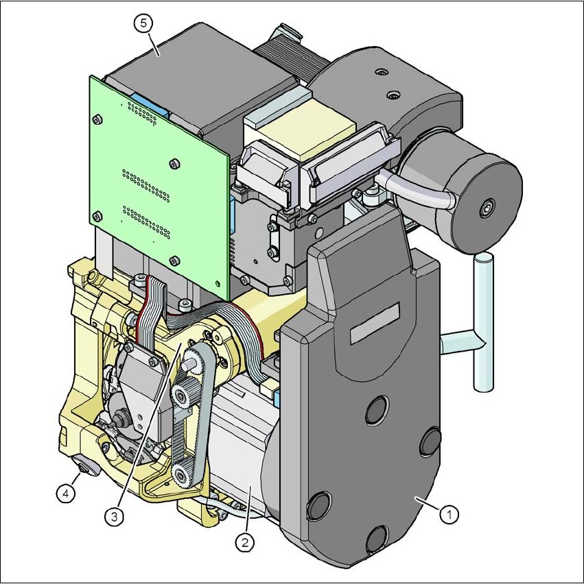
Fig. 3.6 - 2 12-segment Collect&Place head - Function groups, part 2
3
(1) Intermediate distributor board (beneath the cover)
(2) Star drive - DR motor
(3) Z axis motor
(4) Valve adjustment drive
(5) C&P component camera
3.6.1.1 Description
The 12-segment Collect&Place head works on the Collect&Place principle. This means that, with-
in each cycle, twelve components are picked up by the placement head, are optically centered on
the way to the placement position and are rotated into the required placement angle. They are
User Manual SIPLACE D1/D2 3 Technical data for the machine
From software version SR.605.xx 07/2008 EN Edition 3.6 Placement head
113
then set down gently and accurately on the PCB with a blast of air. The twelve nozzles on
SIPLACE Collect&Place heads turn about a horizontal axis, in contrast to conventional chip
shooters. This does not simply save space: the small diameter means that substantially smaller
centrifugal forces occur in comparison to conventional chip shooters. This largely eliminates the
risk of components slipping during transportation.
And there is yet another benefit: the cycle time of the Collect&Place head is the same for all com-
ponents, which means that the placement rate is not dependent on the component size.
3.6.1.2 Technical data
3
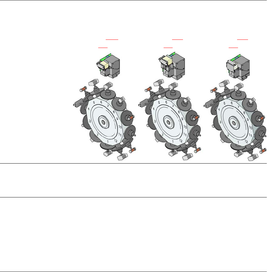
12-segment Col-
lect&Place head with
CO camera type 28,
18 x 18, digital
(see Section 3.9.1
, page
138
)
12-segment Col-
lect&Place head with
CO camera type 29,
27 x 27, digital
(see Section 6.12
, page
304
)
12-segment Col-
lect&Place head with
CO camera type 38,
16 x 16, digital
(see Section 6.13
, page
305
)
Range of components
a
0402 to PLCC44, BGA,
μBGA, flip-chip, TSOP,
QFP, SO to SO32,
DRAM
0201
b
to flip-chip, bare
die, PLCC44, BGA,
*BGA, TSOP, QFP, SO
to SO32, DRAM
01005
c
to 16 x 16 mm²
Component specification
Max. height
Min. lead pitch
Min. lead width
Min. ball pitch
Min. ball diameter
Min. dimensions
Max. dimensions
Max. weight
6 mm
0.5 mm
0.2 mm
0.35 mm
0.2 mm
1.0 x 0.5 mm²
18.7 x 18.7 mm²
2 g
6 mm
0.3 mm
0.15 mm
0.25 mm
0.14 mm
0.6 x 0.3 mm²
b
18.7 x 18.7 mm²
2 g
6 mm
0.25 mm
0.1 mm
0.25 mm
0.14 mm
0.4 x 0.2 mm²
16 x 16 mm²
2 g