00195741-0102_UM_D1_D2_SR605_EN.pdf - 第16页
1 Introduction User Manual SIPLACE D1/D2 1.1 Description of the machine From software version SR.605.xx 07/2008 EN Edition 16 1.1 Description of the machine 1.1.1 SIPLACE D1 placement machine The D1 placement machine is …
User Manual SIPLACE D1/D2 1 Introduction
From software version SR.605.xx 07/2008 EN Edition
15
1 Introduction
These operating instructions provide a manual or reference work for operating and setting up the
SIPLACE
®
D1 and D2 placement machines.
The header of each chapter contains the release and software version, to which this manual ap-
plies.
1
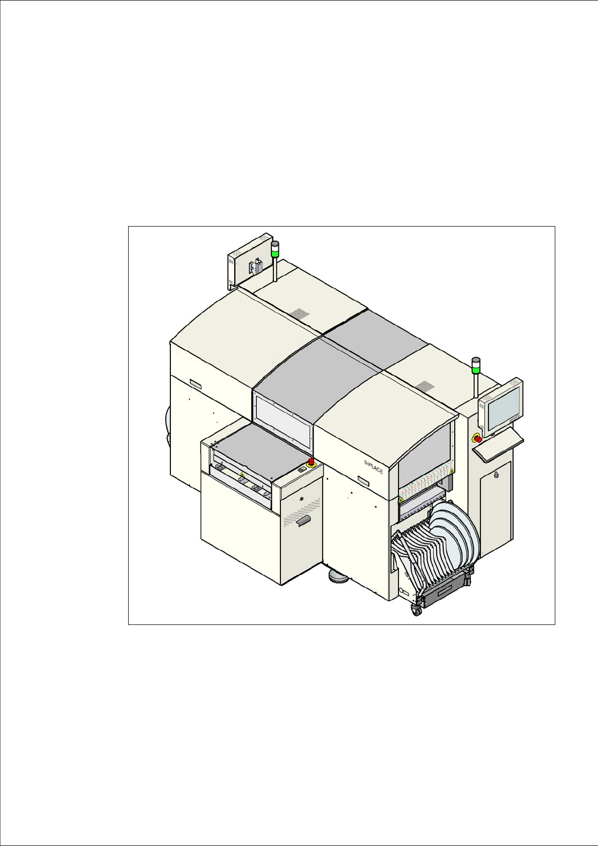
Fig. 1.0 - 1 Placement machine SIPLACE D1/D2
1 Introduction User Manual SIPLACE D1/D2
1.1 Description of the machine From software version SR.605.xx 07/2008 EN Edition
16
1.1 Description of the machine
1.1.1 SIPLACE D1 placement machine
The D1 placement machine is based on the proven SIPLACE platform with its Collect&Place
heads, Pick&Place heads and the SIPLACE S feeder modules. With the new SIPLACE software
and the latest flexible dual conveyor, the D1 offers a range of applications with an attractive price/
performance ratio.
The SIPLACE D1 placement machine is equipped with a gantry that positions the Collect&Place
and Pick&Place heads with precision in the X and Y directions. A 6 or 12-segment Collect&Place
head and/or a Pick&Place head may be set up to suit the placement job.
The following configurations are possible:
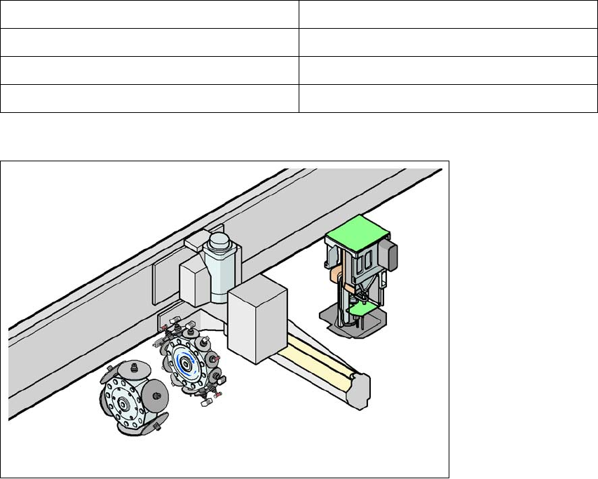
1
Fig. 1.1 - 1 Head modularity - SIPLACE D1
The SIPLACE D1 placement machine is prepared to place 01005 components as standard. For
placement of 01005 components you simply need the optional 01005 package for the 12-segment
Collect&Place head.
Gantry 1 (dual head configuration) Gantry 1 (single head configuration)
C&P12 / P&P C&P12
C&P6 / P&P C&P6
P&P
Tab. 1.1 - 1 Placement head configurations on the D1 machine
C&P12
C&P6
G1
P&P
P1

User Manual SIPLACE D1/D2 1 Introduction
From software version SR.605.xx 07/2008 EN Edition 1.1 Description of the machine
17
The SIPLACE D1 placement machine processes a wide range of components (from 01005 to 125
x 10 mm²) with excellent accuracy. The placement technology is based on the Collect&Place and
Pick&Place principles. Using the head modularity principle developed by SIPLACE, the Col-
lect&Place heads can be changed very quickly indeed.
Digital vision modules perform the optical centering of the components. There are digital cameras
with different resolutions available: standard cameras and high-resolution component cameras.
The coplanarity module tests the coplanarity of the leads of fine pitch components.
Two component trolleys can be docked into SIPLACE D1 machines for providing components. It
is also possible to set up a waffle-pack changer in place of one of the component trolleys.
A three-part PCB conveyor, consisting of input belt, processing belt and output belt, carries the
PCB into the processing position. As a further variant, it is also possible to choose between the
single conveyor or flexible dual conveyor with fixed side on right or left. The flexible dual conveyor
can also be easily reconfigured to form a single conveyor.
The PCBs are optically centered with the digital PCB camera.
1
1
1.1.2 SIPLACE D2 placement machine
The SIPLACE D2 placement machine is equipped with two gantries that position the two Col-
lect&Place heads independently of one another with precision in the X and Y directions. The
placement technology is based on the Collect&Place principle. A 6 or 12-segment Collect&Place
head may be set up at the gantries to suit the placement job.
The following configurations are possible:
PLEASE NOTE 1
To achieve optimum placement rates for different head types, we recommend to set up the place-
ment head with the higher number of segments on the gantry on the side of the stationary PCB
conveyor rail.
Gantry 1 Gantry 2
C&P12 C&P12
C&P12 C&P6
C&P6 C&P12
C&P6 C&P6
Tab. 1.1 - 2 Placement head configurations on the D2 machine