00195741-0102_UM_D1_D2_SR605_EN.pdf - 第258页
5 Tasks for the operating personnel User Manual SIPLACE D1/D2 5.10 Docking the component trolley in or out From software version SR.605.xx 07/2008 EN Edition 258 5.10.3 Docking in the component tro lley PLEASE NOTE 5 Sho…
User Manual SIPLACE D1/D2 5 Tasks for the operating personnel
From software version SR.605.xx 07/2008 EN Edition 5.10 Docking the component trolley in or out
257
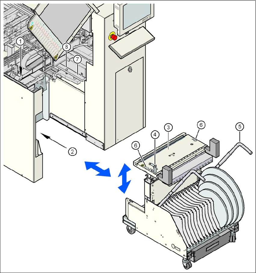
Fig. 5.10 - 2 Docking the component trolley in or out
5
(1) Button for raising the component table
(2) Plug for connecting the component trolley cable
(3) Component table (can be raised or lowered)
(4) Button for lowering the component table
(5) component trolley handle
(6) Centering hole for the centering pins
(7) Supporting surface for the component table (right and left)
(8) Centering pin for the component table
5 Tasks for the operating personnel User Manual SIPLACE D1/D2
5.10 Docking the component trolley in or out From software version SR.605.xx 07/2008 EN Edition
258
5.10.3 Docking in the component trolley
PLEASE NOTE 5
Shorten the component tapes on the front end of the S feeder modules to approximately 1 cm
before you dock in the component trolley.
CAUTION 5
Check that the placement head is outside the range of the component trolley.
→ Check that the left and right contact surfaces (item 7 in Fig. 5.10 - 2
, page 257) in the machine
for the component table are clean.
→ Check that the contact surfaces on the underside of the component table are clean.
→ CAREFULLY push the component trolley into the machine.
→ Plug the connecting cable of the component trolley into the socket (item 2 in Fig. 5.10 - 2
,
page 257
) on the machine.
→ Turn the switch on the component table (item 4 in Fig. 5.10 - 2
, page 257) up.
→ Press the button until the component table has reached the upper final position (item 1 in Fig.
5.10 - 2
, page 257).
→ Carefully push the component trolley into machine as far as the stop.
→ Check that the centering holes in the component table bed lie precisely over the centering
pins of the machine (item 8 in Fig. 5.10 - 2
, page 257).
WARNING DANGER OF CRUSHING 5
When lowering the component table bed, never reach into the gap between the feeders and
the used tape channel. 5
→ Turn the switch on the component table (item 4 in Fig. 5.10 - 2
, page 257) down.
The component table is lowered.
→ Ensure that the centering pins engage in the centering holes in the component table and that
the component table is fully lowered.
→ Close the protective cover.
→ Press the start button to start the machine.
User Manual SIPLACE D1/D2 5 Tasks for the operating personnel
From software version SR.605.xx 07/2008 EN Edition 5.10 Docking the component trolley in or out
259
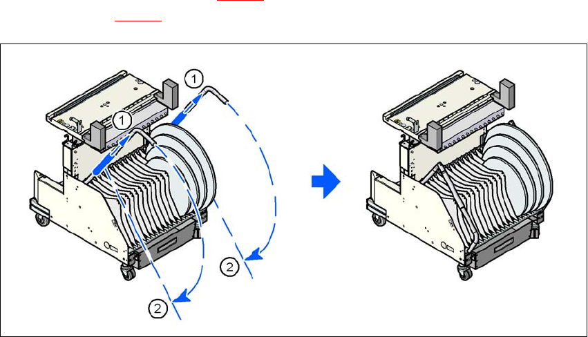
→ Push the sleeve (item 1 in Fig. 5.10 - 3) up using both handles and swivel the handle down
(item 2 in Fig. 5.10 - 3
).
5
Fig. 5.10 - 3 Component trolley - swivel handles down
(1) Push sleeve up
(2) Fold handle down