00195741-0102_UM_D1_D2_SR605_EN.pdf - 第279页
User Manual SIPLACE D1/D2 6 Station extensions From software version SR.605.xx 07/2008 EN Edition 6.2 Waffle-pack changer (WPC) 279 6.2 W affle-p ack changer (WPC) Item no. 001 19825-xx WPC4 on the SIPLACE D-series 6.2.1…
6 Station extensions User Manual SIPLACE D1/D2
6.1 Nozzle changer From software version SR.605.xx 07/2008 EN Edition
278
Special nozzles are available for all placement heads in order to process placement jobs with max-
imum speed, precision and flexibility. The use of automatic nozzle changers also reduces the set-
up times that occur at a product change.
SIPLACE Company can provide mechanical grippers for Pick&Place heads. If a component's sur-
face is not suitable for sucking up with nozzles, then it can be picked up and placed with mechan-
ical grippers. There are two types of gripper, and their functions can be divided into two groups:
– Grippers that grip the component at its outer edges and
– Grippers that grip the component at its inner edge.
Information on special nozzles and grippers is available from SIPLACE Company. For the produc-
tion of special magazines and grippers, again contact SIPLACE Company.
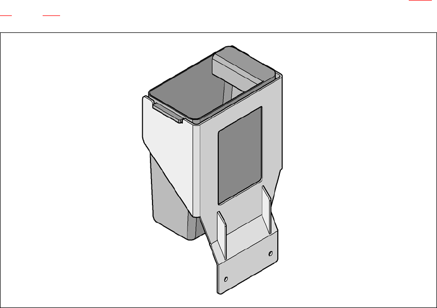
6.1.3.6 Component reject bin
A component reject bin may be installed for the SIPLACE Pick&Place head (item 4 in Fig. 6.1 -
12, page 277). It is positioned beside the nozzle changer at location 2 on the D1 machine.
6
Fig. 6.1 - 13 Component reject bin

User Manual SIPLACE D1/D2 6 Station extensions
From software version SR.605.xx 07/2008 EN Edition 6.2 Waffle-pack changer (WPC)
279
6.2 Waffle-pack changer (WPC)
Item no. 00119825-xx WPC4 on the SIPLACE D-series
6.2.1 Safety instructions
WARNING 6
→ Never reach into the gaps between the waffle-pack changer and the machine base while the
machine is running.
→ The waffle-pack changer control cable must only then be connected to the connecting socket
or taken from this if the waffle-pack changer is docked into the machine.
→ The power supply cable must not be plugged into or unplugged from the external power sup-
ply unless the waffle-pack changer is docked into the machine.
→ The waffle-pack changer must NOT be operated unless it is docked into the machine.
6.2.2 Description
The waffle-pack changer makes components available in the waffle-pack trays to avoid unneces-
sary loss of time during storage and automatic changing of the waffle-pack trays.
Programmable, random access to up to 28 waffle-pack trays also increases the range of compo-
nents that can be made available.
The waffle-pack changer has an integral chassis, and is easy to move to other locations. It is sup-
plied with the PCB conveyor height implemented for the machines, but can also be adapted for
the 830, 900, 930 and 950 mm PCB conveyor heights with just a few simple operations. There are
5 locations for 30 mm width S feeder modules available on the component table.

6 Station extensions User Manual SIPLACE D1/D2
6.2 Waffle-pack changer (WPC) From software version SR.605.xx 07/2008 EN Edition
280
6.2.3 Technical data
6.2.3.1 Dimensions, weight
6.2.3.2 Electrical ratings
Dimensions (L x W) 1560 x 360 mm²
Height
830 mm ± 15 mm PCB conveyor height
900 mm ± 15 mm PCB conveyor height
930 mm ± 15 mm PCB conveyor height
950 mm ± 15 mm PCB conveyor height
1360 mm ± 15 mm
1430 mm ± 15 mm
1460 mm ± 15 mm
1480 mm ± 15 mm
Weight approx. 240 kg
Load per unit area 4.19 kN/m²
Dimensions of the waffle-pack tray carrier (L x W x H) 360 x 260 x 6 mm³
Weight of the waffle-pack tray carrier 0.8 kg
Dimensions of the waffle-pack tray, including components 341 x 235 x 15 mm³
max. 341 x 235 x 23 mm³
Weight of the waffle-pack tray carrier, including waffle-pack tray
and components max. 1.2 kg
Storage capacity max. 28 WTC
Total weight of the 28 waffle-pack tray carriers 27.6 kg
Weight of magazine storage unit, waffle-pack tray carrier, waffle-
pack trays and components max. 50 kg
Changeover time for waffle-pack tray carriers
over 1 level
over 10 levels
over 27 levels
1.9 s
2.3 s
2.9 s
Supply voltage 3 x 200 VAC ± 5%; 50/60 Hz (Japanese version)
3 x 208 VAC ± 5%; 50/60 Hz (U.S.A. version)
3 x 230 VAC ± 5 %; 50/60 Hz
3 x 380 VAC ± 5 %; 50/60 Hz
3 x 400 VAC ± 5 %; 50/60 Hz (European version)
3 x 415 VAC ± 5 %; 50/60 Hz
Nominal apparent power 800 VA
Rated current 0.7 A at 3 x 400 VAC
Fuse 3 x 10 or 3 x 16 A