00195741-0102_UM_D1_D2_SR605_EN.pdf - 第237页
User Manual SIPLACE D1/D2 5 Tasks for the operating personnel From software version SR.605.xx 07/2008 EN Edition 5.2 Controls and displays 237 5.2.3 Description All the controls can be reache d by a 1.40 m tall person . …
5 Tasks for the operating personnel User Manual SIPLACE D1/D2
5.2 Controls and displays From software version SR.605.xx 07/2008 EN Edition
236
5.2.2 Position - part 2
5
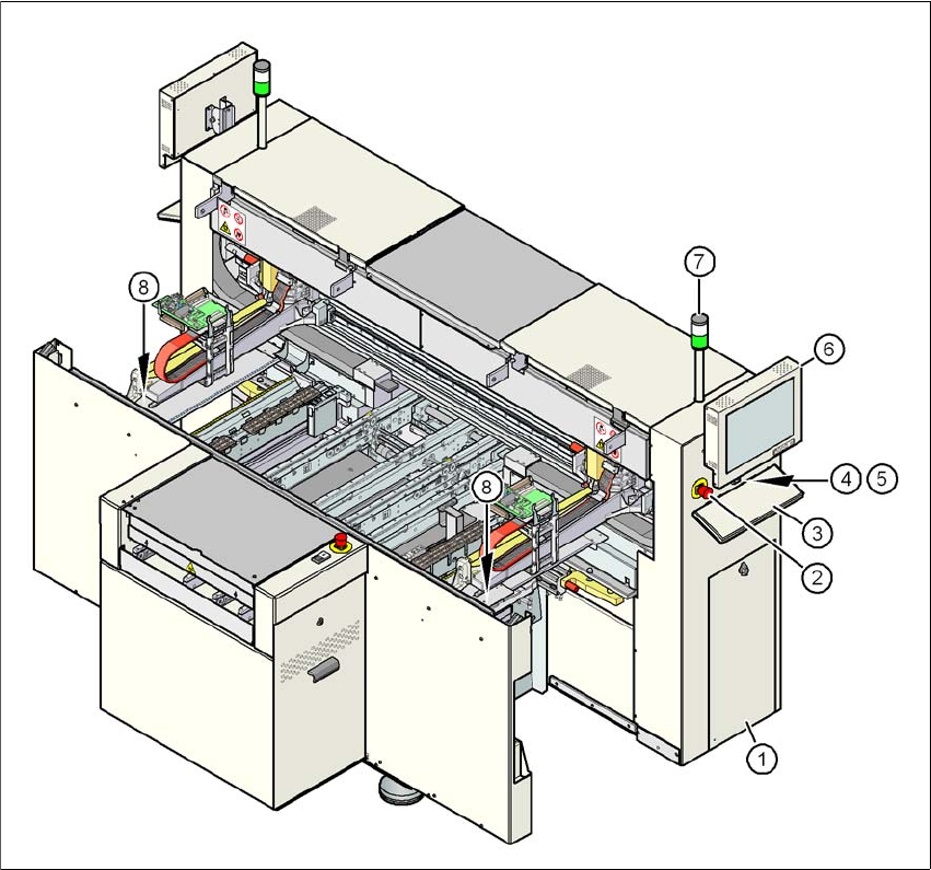
Fig. 5.2 - 2 Controls and displays - part 2
(1) Operator panel on the pneumatic side
(2) EMERGENCY STOP button
(3) Keyboard
(4) Start button (white)
(5) Stop button (black)
(6) LCD touchscreen
(7) Indicator lamp
(8) Button for raising the component table
User Manual SIPLACE D1/D2 5 Tasks for the operating personnel
From software version SR.605.xx 07/2008 EN Edition 5.2 Controls and displays
237
5.2.3 Description
All the controls can be reached by a 1.40 m tall person.
Main power switch 5
The main power switch is used to switch the power supply to the machine on and off.
WARNING
Some parts inside the machine carry potentially lethal voltages - even when switched off at the
main power switch. 5
Stop button 5
This button is used to stop the machine.
Start button 5
This button starts the machine after it has been switched on or after faults have been eliminated.
EMERGENCY STOP button 5
The EMERGENCY STOP button latches in the ON position when pressed. The power supply to
the gantry axes, the star axes of the placement heads, conveyors and used tape cutters is inter-
rupted. The external safety circuits are interrupted. Turn the button to release it.
Component counter 5
The component counter displays the number of components processed.
LCD touchscreen 5
There is a flat screen on either side of the machine.
Keyboard 5
The keyboard is located beneath the monitor.
Indicator lamps 5
The sequence of colors of the indicator lamps is white - green. These lamps are used to signal
operating statuses and malfunctions of the machine.

5 Tasks for the operating personnel User Manual SIPLACE D1/D2
5.2 Controls and displays From software version SR.605.xx 07/2008 EN Edition
238
5.2.4 Ergonomic arrangement of the controls
Figures 5.2 - 1, page 235 and 5.2 - 2, page 236 provide an overview of the positions of the con-
trols. They are subdivided into the following groups:
Operator panel on the right-hand side (pneumatic unit) of the center console: 5
– LCD touchscreen
– Keyboard with trackball
– Start button, stop button
Operator panel on the left-hand side (power supply unit) of the center console: 5
– LCD touchscreen
– Keyboard with trackball
– Component counter
– Start button
– Stop button
– Main power switch
PCB conveyor input side: 5
– EMERGENCY STOP button
– Start button, stop button
Machine frame beneath the protective covers: 5
– Button for raising the component table for locations 1 and 2
5
5
5
5
5.2.4.1 Controls on the machine's operator panels
The two operator panel have identical control functions.
Monitor, keyboard, emergency stop button, start and stop buttons 5
There is a LCD touchscreen and a keyboard on both sides of the machine. The start and stop but-
tons are located beneath the LCD screen. The on-screen dialog will occasionally prompt you to
activate certain actions using buttons, and this arrangement will make it easier for you both to ac-
tivate and to interactively control these actions. Each operator panel has an emergency stop but-
ton to allow a fast response in an emergency.