00195741-0102_UM_D1_D2_SR605_EN.pdf - 第147页
User Manual SIPLACE D1/D2 3 Technical data for the machine From software version SR.605.xx 07/2008 EN Edition 3.10 Feeder modules 147 3.10.8 T echnical data for the S feeder modules The following pages co ntain pictures …

3 Technical data for the machine User Manual SIPLACE D1/D2
3.10 Feeder modules From software version SR.605.xx 07/2008 EN Edition
146
3.10.6 Manual removal of tantalum capacitors that were not picked up by the
operator
To ensure that tantalum capacitors do not cause the tape material to burn when it is cut as a result
of pick-up errors, the user interface has been extended to include the "Remove component from
tape in the event of a pick-up error" option. This option must be enabled in SIPLACE Pro. On the
placement machine, the component that was not picked up is paced forward again until it is ready
for removal from the component tape. The track is deactivated and the operator is sent an error
message to remind him to pick up the tantalum component from the tape.
If an alternative track is available, the machine continues placing. The operator is able to stop the
machine, however, and pick up the tantalum component.
If no alternative track is available and it is not possible to continue placement with other compo-
nents, the machine will stop. At this point, the operator can again remove the tantalum component
and acknowledge the error. Once the operator has restarted the machine, placement is continued
and components are picked up from the track that is now enabled once more.
PLEASE NOTE 3
This software function is also a good idea for high-quality components.
PLEASE NOTE
Please follow the safety instructions for processing capacitors based on powdered metal in Sec-
tion 2.5.5, page 61.
3.10.7 Splice sensors for S tape feeder modules
Splice sensors can be retrofitted to the S tape feeder modules.
Splice sensor for an S tape feeder module Item no.
2 x 8 mm S 00141205-xx
3 x 8 mm S 00141206-xx
12/16 mm S 00141207-xx
24/32 mm S 00141208-xx
44 mm S 00141209-xx
56 mm S 00141211-xx
72 mm S 00141212-xx
88 mm S 00141213-xx
User Manual SIPLACE D1/D2 3 Technical data for the machine
From software version SR.605.xx 07/2008 EN Edition 3.10 Feeder modules
147
3.10.8 Technical data for the S feeder modules
The following pages contain pictures of all the S feeder modules, the technical data and the op-
tions for setting up the feeder modules on the machine.
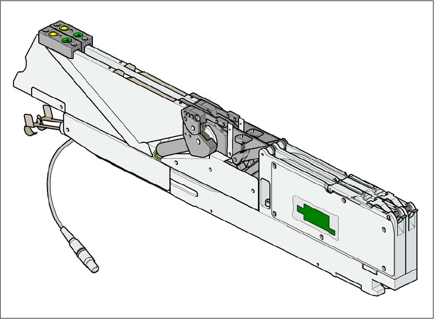
3.10.8.1 8 mm SII tape feeder module
3
Fig. 3.10 - 1 8 mm SII tape feeder module
3
Item no. 00141096-xx 3
Width 30.6 mm 3
Tracks per feeder module 2 3
Feeder module locations filled 1 3
Max. number of feeder modules per machine 2 x 15 3
Stock of components for 7" reels Approx. 4,000 3
Conveyor increment 2mm / 4mm 3
Tape material Paper or blister tapes 3
Max. component height 2.5 mm 3
3 Technical data for the machine User Manual SIPLACE D1/D2
3.10 Feeder modules From software version SR.605.xx 07/2008 EN Edition
148
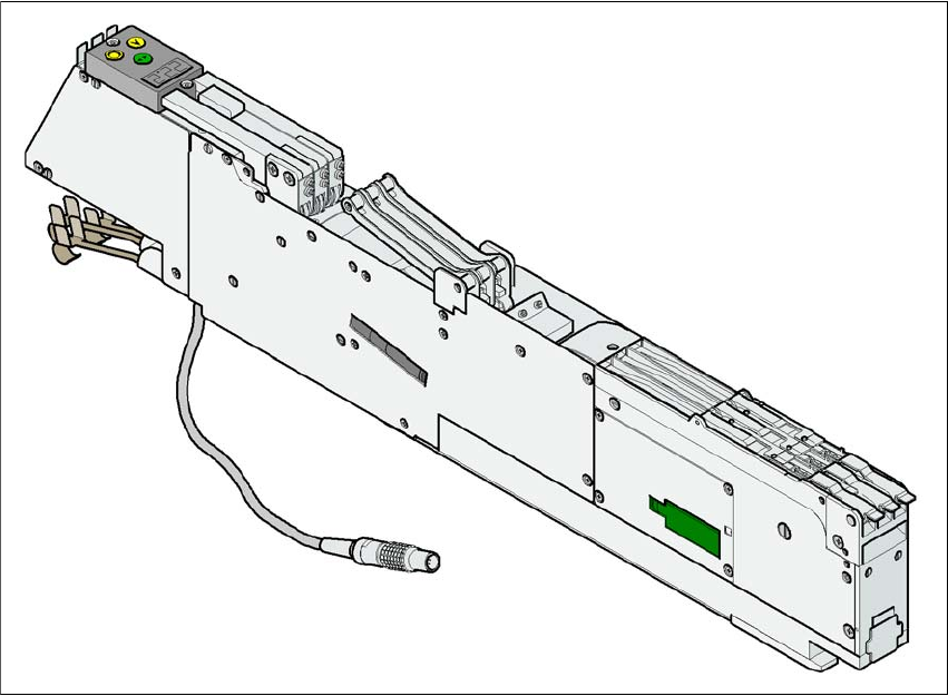
3.10.8.2 3 x 8 mm S tape feeder module
Fig. 3.10 - 2 3 x 8 mm S tape feeder module
Item no. 00141098-xx 3
Width 30.6 mm 3
Tracks per feeder module 3 3
Feeder module locations filled 1 3
Max. number of feeder modules per machine 2 x 15 3
Stock of components for 7" reels Approx. 4,000 to 10,000 3
Conveyor increment 2 mm / 4 mm / 8 mm 3
Tape material Paper or blister tapes 3
Max. component height 2.5 mm 3