00195741-0102_UM_D1_D2_SR605_EN.pdf - 第15页
User Manual SIPLACE D1/D2 1 Introduction From software version SR.605.xx 07/2008 EN Edition 15 1 Introduction These operating instructions pro vide a manual or refere nce work for oper ating and settin g up the SIPLACE ®…
Content User Manual SIPLACE D1/D2
07/2008 EN Edition
14
User Manual SIPLACE D1/D2 1 Introduction
From software version SR.605.xx 07/2008 EN Edition
15
1 Introduction
These operating instructions provide a manual or reference work for operating and setting up the
SIPLACE
®
D1 and D2 placement machines.
The header of each chapter contains the release and software version, to which this manual ap-
plies.
1
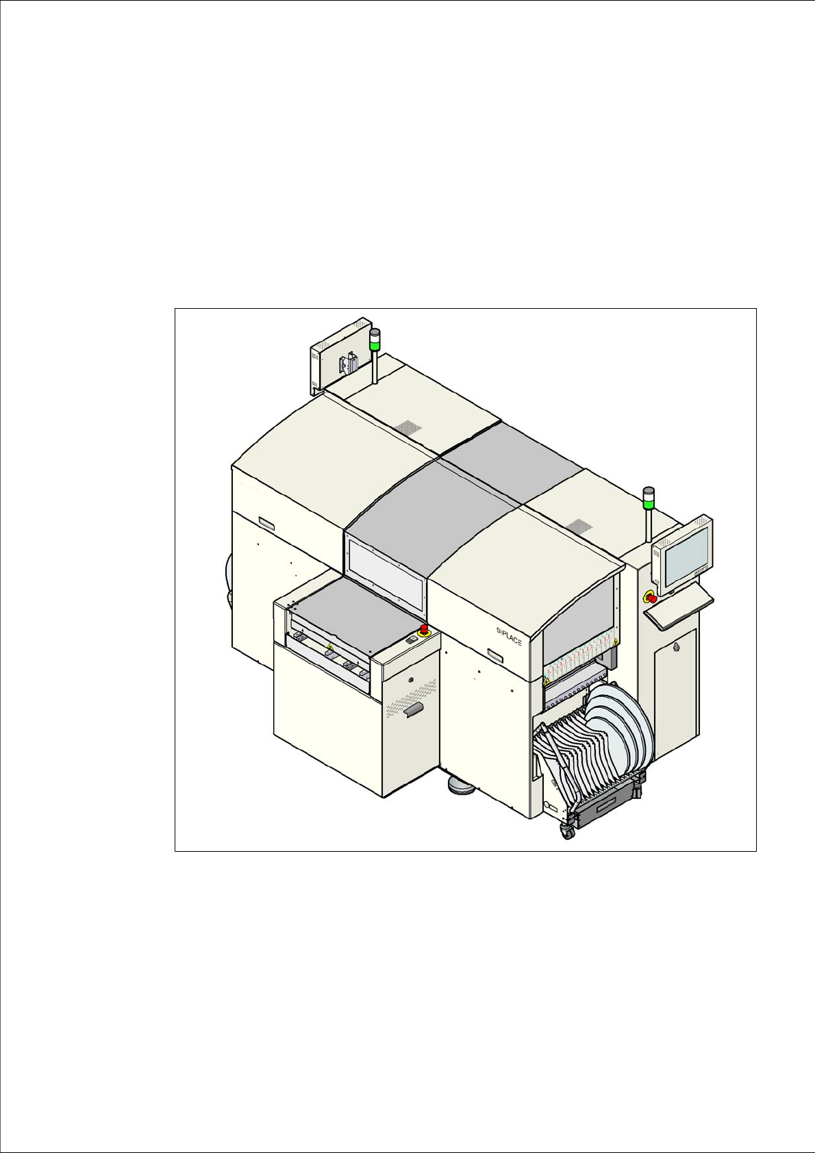
Fig. 1.0 - 1 Placement machine SIPLACE D1/D2
1 Introduction User Manual SIPLACE D1/D2
1.1 Description of the machine From software version SR.605.xx 07/2008 EN Edition
16
1.1 Description of the machine
1.1.1 SIPLACE D1 placement machine
The D1 placement machine is based on the proven SIPLACE platform with its Collect&Place
heads, Pick&Place heads and the SIPLACE S feeder modules. With the new SIPLACE software
and the latest flexible dual conveyor, the D1 offers a range of applications with an attractive price/
performance ratio.
The SIPLACE D1 placement machine is equipped with a gantry that positions the Collect&Place
and Pick&Place heads with precision in the X and Y directions. A 6 or 12-segment Collect&Place
head and/or a Pick&Place head may be set up to suit the placement job.
The following configurations are possible:
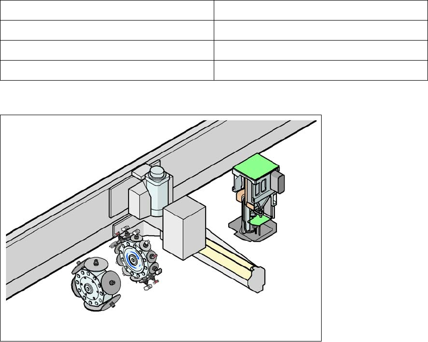
1
Fig. 1.1 - 1 Head modularity - SIPLACE D1
The SIPLACE D1 placement machine is prepared to place 01005 components as standard. For
placement of 01005 components you simply need the optional 01005 package for the 12-segment
Collect&Place head.
Gantry 1 (dual head configuration) Gantry 1 (single head configuration)
C&P12 / P&P C&P12
C&P6 / P&P C&P6
P&P
Tab. 1.1 - 1 Placement head configurations on the D1 machine
C&P12
C&P6
G1
P&P
P1