00195741-0102_UM_D1_D2_SR605_EN.pdf - 第88页
2 Operational safety User Manual SIPLACE D1/D2 2.9 Energy state of the machine after switching off at the main po wer switch From software version SR.605.xx 07/2008 EN Edition 88 2 Fig. 2.9 - 2 Power supply unit, front v…
User Manual SIPLACE D1/D2 2 Operational safety
From software version SR.605.xx 07/2008 EN Edition 2.9 Energy state of the machine after switching off at the main power switch
87
2.9.1 Machine switched off at the main switch, but still connected
WARNING
The following components still carry potentially lethal voltages even if the main power switch is
switched off:
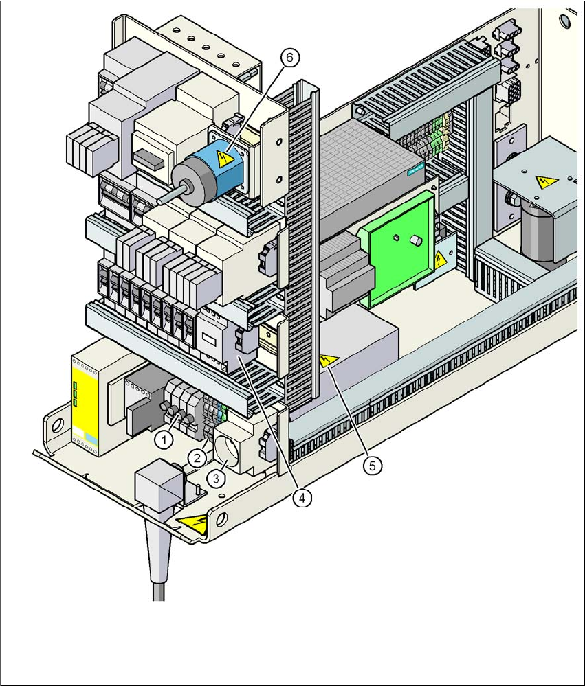
– Infeed terminals X100 (item 2 in Fig. 2.9 - 2
, page 88)
– Discharge reactor Z2 (item 4 in Fig. 2.9 - 2
, page 88)
– Fuses FU, FV, FW and FBU (item 1 in Fig. 2.9 - 2
, page 88)
– Line filter Z1 (item 5 in Fig. 2.9 - 2
, page 88)
– Service socket BU1 (item 3 in Fig. 2.9 - 2
, page 88)
– Cable connection terminals 1, 3, and 5 of the S1 main power switch (item 1 in Fig. 2.9 - 1
,
page 86
) and item 6 in Fig. 2.9 - 2, page 88)
– The color of all individual wires, which still carry potentially lethal voltages even if the main
power switch is switched off, is brown.
– Axis unit (Fig. 2.2 - 9, page 52)
2 Operational safety User Manual SIPLACE D1/D2
2.9 Energy state of the machine after switching off at the main power switch From software version SR.605.xx 07/2008 EN Edition
88
2
Fig. 2.9 - 2 Power supply unit, front view
(1) Fuses FU, FV, FW (discharge reactor Z2) and FBU (service socket BU1)
(2) Infeed terminals X100
(3) BU1 service socket
(4) Discharge reactor Z2
(5) Line filter Z1
(6) Main power switch S1
User Manual SIPLACE D1/D2 2 Operational safety
From software version SR.605.xx 07/2008 EN Edition 2.9 Energy state of the machine after switching off at the main power switch
89
The following table specifies the voltages of modules when the machine is switched off at the main
switch, but still connected to the mains supply.
2
2.9.2 Machine switched off at the main power switch and disconnected
The machine is unpowered, apart from slight residual voltages in the power supply unit.
2.9.3 Compressed air conditions in the machine after switching off at the main
power switch
When the system is switched off at the main power switch (item 1 in Fig. 2.9 - 2, page 88) or if the
power supply fails, the electrically-controlled main valve Y1 of the compressed air unit closes (item
1 in Fig. 2.8 - 1
, page 85). The pressure will drop to 0 MPa (0 bar) within 5 seconds.
Module Voltage
Infeed terminals X100
Discharge reactor Z2
Fuses FU, FV, FW
Line filter Z1: terminals L1, L2, L3, L1’, L2’, L3’
3 x 200 VAC
3 x 208 VAC
3 x 230 VAC
3 x 380 VAC
3 x 400 VAC
3 x 415 VAC
Service socket BU1
Fuse FBU
115 VAC
120 VAC
130 VAC
220 VAC
230 VAC
240 VAC
Main power switch S1
Terminals 1, 3, 5
3 x 200 VAC
3 x 208 VAC
3 x 230 VAC
3 x 380 VAC
3 x 400 VAC
3 x 415 VAC
Main power switch S1
Terminals 2, 4, 6 0 VAC
Power supply unit
(see Fig. 2.9 - 2
, page 88)
Pin X14 (200V)
Pin X15(GND)
Terminal X8:1 measured to X15
< 60 VDC
< 60 VDC
within 4 s
within 1 s