00195741-0102_UM_D1_D2_SR605_EN.pdf - 第207页
User Manual SIPLACE D1/D2 4 Setting up and commissioning From software version SR.605.xx 07/2008 EN Edition 4.3 Setting up the machine 207 4.3.4.1 Sp acers for the PCB conveyor height s of 900 / 930 / 950 mm There are di…
4 Setting up and commissioning User Manual SIPLACE D1/D2
4.3 Setting up the machine From software version SR.605.xx 07/2008 EN Edition
206
→ With the fork-lift, raise the machine approximately 35 cm.
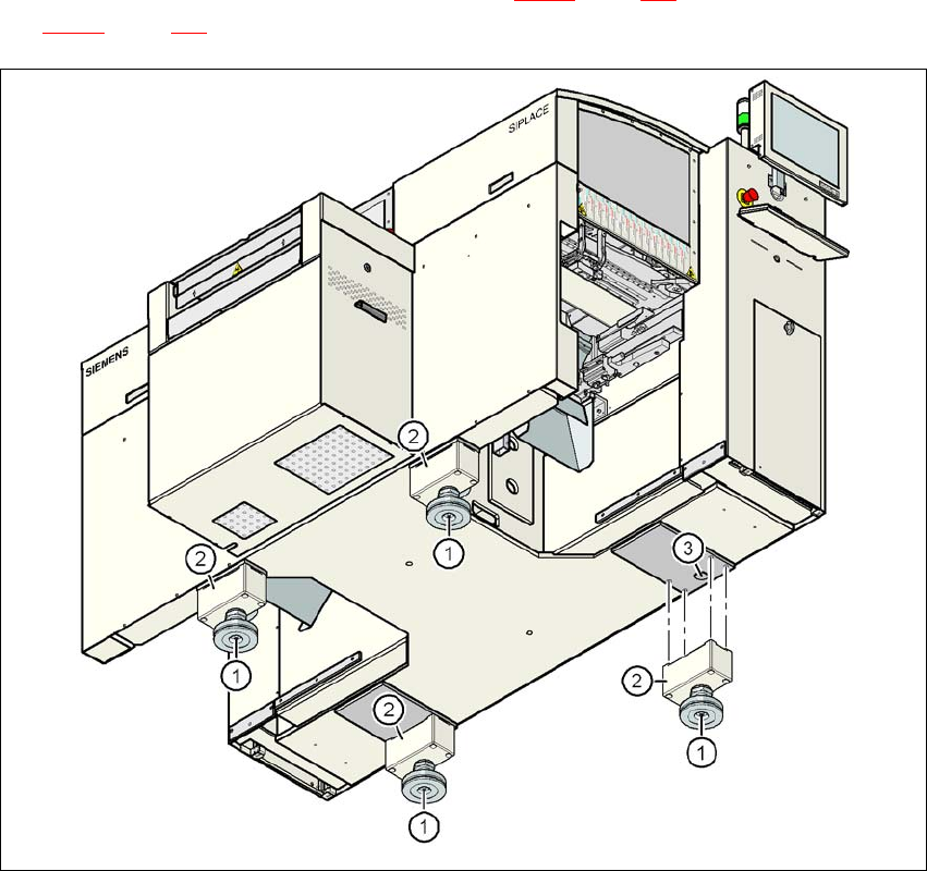
The machine stands on 4 machine feet (item 1 in Fig. 4.3 - 2
, page 206) with 4 spacers (item 2 in
Fig. 4.3 - 2
, page 206) for adjusting the height, if necessary.
4
Fig. 4.3 - 2 Machine feet
(1) Machine foot, 4x
(2) Machine foot, 4x
(3) Hole in the machine frame for the machine foot for the 830 mm PCB conveyor height
User Manual SIPLACE D1/D2 4 Setting up and commissioning
From software version SR.605.xx 07/2008 EN Edition 4.3 Setting up the machine
207
4.3.4.1 Spacers for the PCB conveyor heights of 900 / 930 / 950 mm
There are different spacers (see item 2 in Fig. 4.3 - 2) and fixing screws for the 900 / 930 / 950
mm PCB conveyor height. You will need 4 spacers and 16 fixing screws.
4.3.4.2 Presetting the PCB conveyor height to 830 mm
You will not need a spacer for a PCB conveyor height of 830 mm.
→ Insert the machine feet into the holes in the machine frame (item 4 in Fig. 4.3 - 2
, page 206).
→ Use the M24 nuts to set the height of the machine feet (item 1 in Fig. 4.3 - 2
, page 206) so
that the distance between the underside of the machine foot and the bottom edge of the ma-
chine frame is 115 mm.
→ Hand-tighten the M24 nuts.
4.3.4.3 Presetting the PCB conveyor height to 900 / 930 / 950 mm
→ Then fix the 4 spacers (item 2 in Fig. 4.3 - 2, page 206).
The spacers for the different PCB conveyor heights are listed in Section 4.3.4.1
, page 207.
→ Use the M24 nuts to set the height of the machine feet (item 1 in Fig. 4.3 - 2
, page 206) to the
following values:
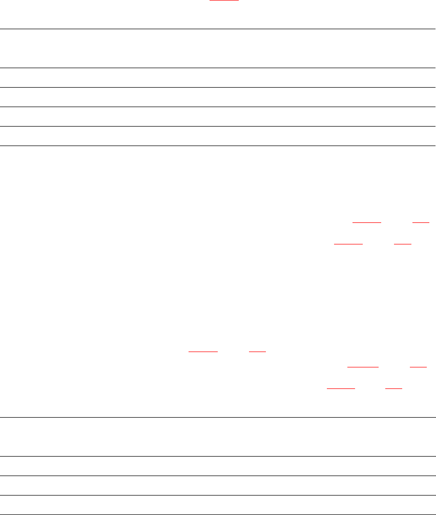
PCB conveyor
height
Spacer, 4x
Item no.
Spacer
Height
Hexagon socket
head screw, 16x
830 mm – – –
900 mm 00344069-xx 70 mm DIN 912 M12x70
930 mm 00344070-xx 100 mm DIN 912 M12x100
950 mm 00331553-xx 122.5 mm DIN 912 M12x100
PCB conveyor height Distance from underside of machine foot to bottom
edge of machine frame
900 mm 185 mm
930 mm 215 mm
950 mm 237 mm
4 Setting up and commissioning User Manual SIPLACE D1/D2
4.3 Setting up the machine From software version SR.605.xx 07/2008 EN Edition
208
4.3.5 Fitting the indicator lamps
→ Remove both upper cover plates.
→ Connect the cables of the indicator lamps to the cables on the basic machine.
→ Insert the indicator lamp into the hole until the tube of the indicator lamp projects sufficiently
into the terminal beneath.
→ Tighten the hexagon socket head screw on the terminal.
→ Fasten both upper cover plates.
4.3.6 Fixing the monitors
→ Fix the monitors and connect the cables.
→ Check the cable connections