00195741-0102_UM_D1_D2_SR605_EN.pdf - 第71页
User Manual SIPLACE D1/D2 2 Operational safety From software version SR.605.xx 07/2008 EN Edition 2.6 Safety equipment 71 2.6.2.2 Position of protective switches on the machine 2 Fig. 2.6 - 6 Position of protective switc…
2 Operational safety User Manual SIPLACE D1/D2
2.6 Safety equipment From software version SR.605.xx 07/2008 EN Edition
70
2
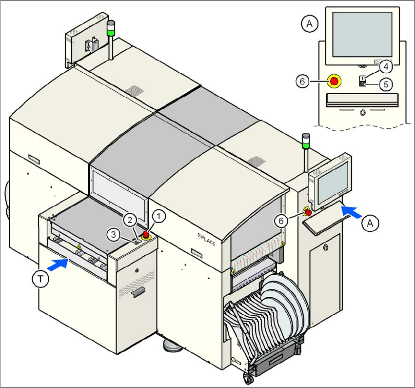
Fig. 2.6 - 5 Position of switches and buttons - View of the PCB input side
(1) EMERGENCY STOP button on the input side
(2) Start button (white) on the input side
(3) Stop button (white) on the input side
(4) Start button (white) on the operator panel on the compressed air unit side
(5) Stop button (black) on the operator panel on the compressed air unit side
(6) Emergency stop button on the operator panel on the compressed air unit side
(T) PCB transport direction
User Manual SIPLACE D1/D2 2 Operational safety
From software version SR.605.xx 07/2008 EN Edition 2.6 Safety equipment
71
2.6.2.2 Position of protective switches on the machine
2
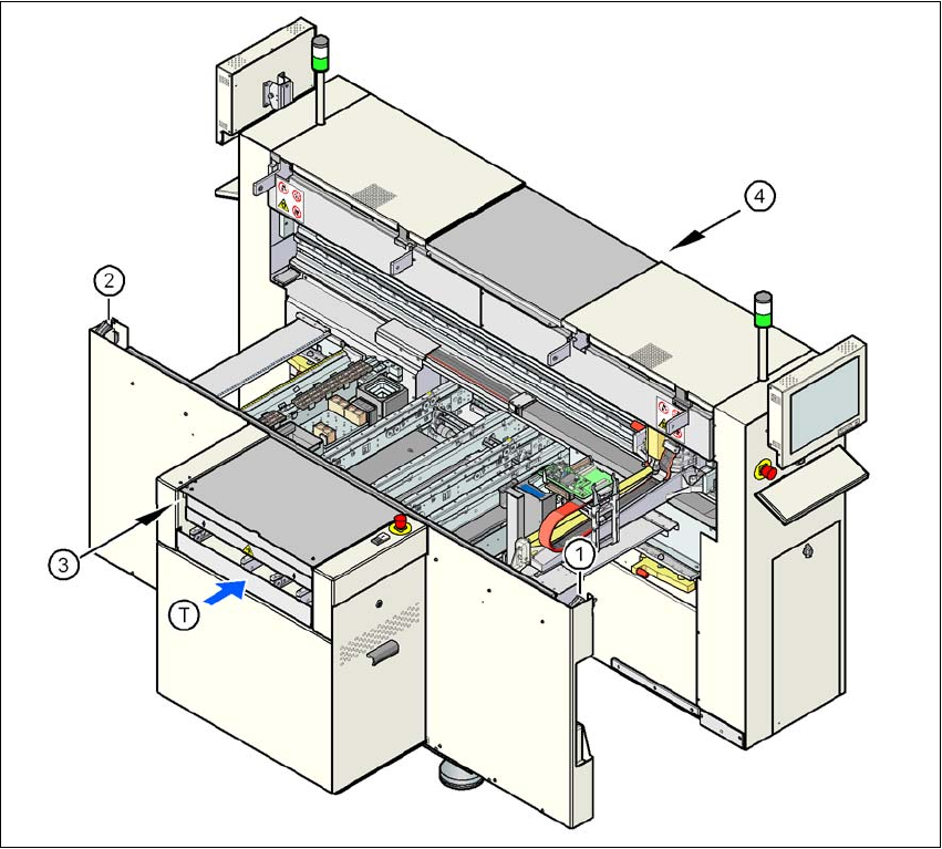
Fig. 2.6 - 6 Position of protective switches on the machine
2
(1) Protective cover switch, location 1
(2) Protective cover switch, location 2
(3) Protective switch for the cover flap on the PCB conveyor input side
(4) Protective switch for the cover flap on the PCB conveyor output side
(T) PCB transport direction
2 Operational safety User Manual SIPLACE D1/D2
2.6 Safety equipment From software version SR.605.xx 07/2008 EN Edition
72
2.6.2.3 Position of control computer, machine controller, connecting sockets and
buttons for the component trolley
2
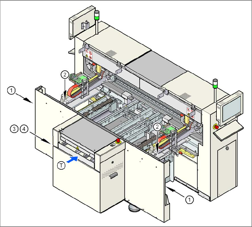
Fig. 2.6 - 7 Control computer, machine controller, connecting sockets and buttons for the component trolley
(1) Socket for connecting the component trolley
(2) Push-button for raising the component table, with the hinged cover flap over it
(3) Control computer
(4) Machine controller
(T) PCB transport direction