00195741-0102_UM_D1_D2_SR605_EN.pdf - 第67页
User Manual SIPLACE D1/D2 2 Operational safety From software version SR.605.xx 07/2008 EN Edition 2.6 Safety equipment 67 2 Fig. 2.6 - 2 Cover flap on the output belt (1) Cover flap on the outp ut belt - swivels inwards …
2 Operational safety User Manual SIPLACE D1/D2
2.6 Safety equipment From software version SR.605.xx 07/2008 EN Edition
66
2.6 Safety equipment
2.6.1 Protective covers
2
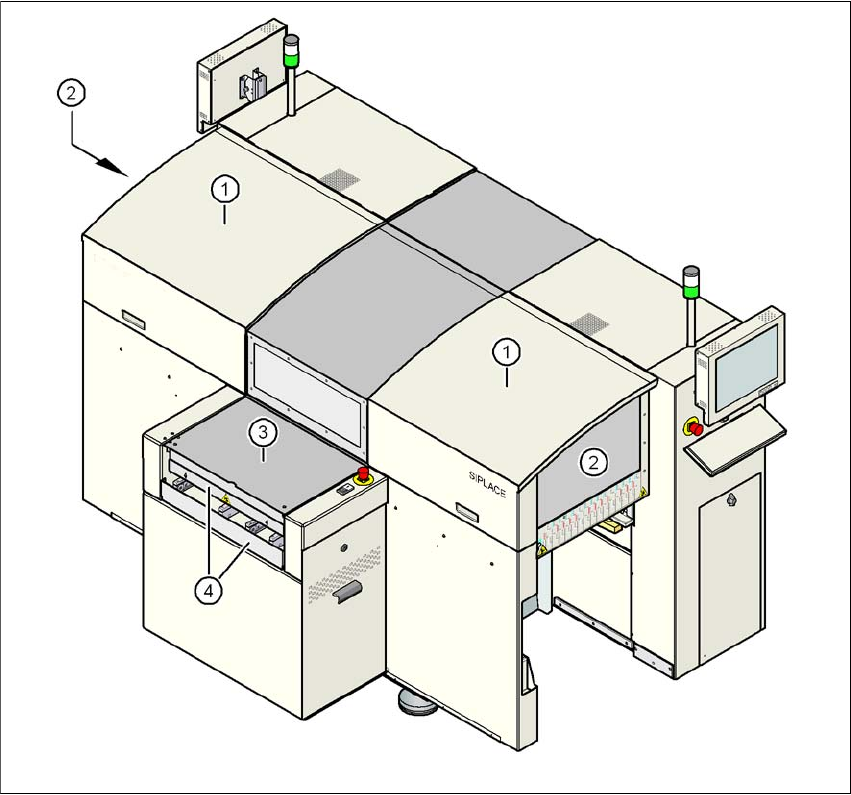
Fig. 2.6 - 1 Protective covers - viewed from the input side
(1) Protective covers
(2) Safety panels
(3) Cover flap on the input belt
(4) Hand guard on the input belt
User Manual SIPLACE D1/D2 2 Operational safety
From software version SR.605.xx 07/2008 EN Edition 2.6 Safety equipment
67
2
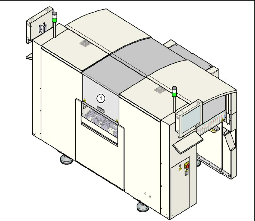
Fig. 2.6 - 2 Cover flap on the output belt
(1) Cover flap on the output belt - swivels inwards
The traveling range of the gantries has two protective covers that can be swung upwards. There
are side screens to prevent access to the inside of the machine from the side. The lift-up hinged
cover over the input belt of the PCB conveyor, the hand guard on the input belt and the hinged
cover flap that swivels inwards on the output belt all prevent access to the PCB conveyor.
Function 2
The power supply to the gantry axes is interrupted immediately if one of the protective covers is
lifted up or the cover flap on the PCB conveyor is raised or swiveled in. The gantry axes stop mov-
ing. The message "Close cover" is displayed on the screen.
→ Close the protective covers and press one of the start buttons to continue placement.
2 Operational safety User Manual SIPLACE D1/D2
2.6 Safety equipment From software version SR.605.xx 07/2008 EN Edition
68
2
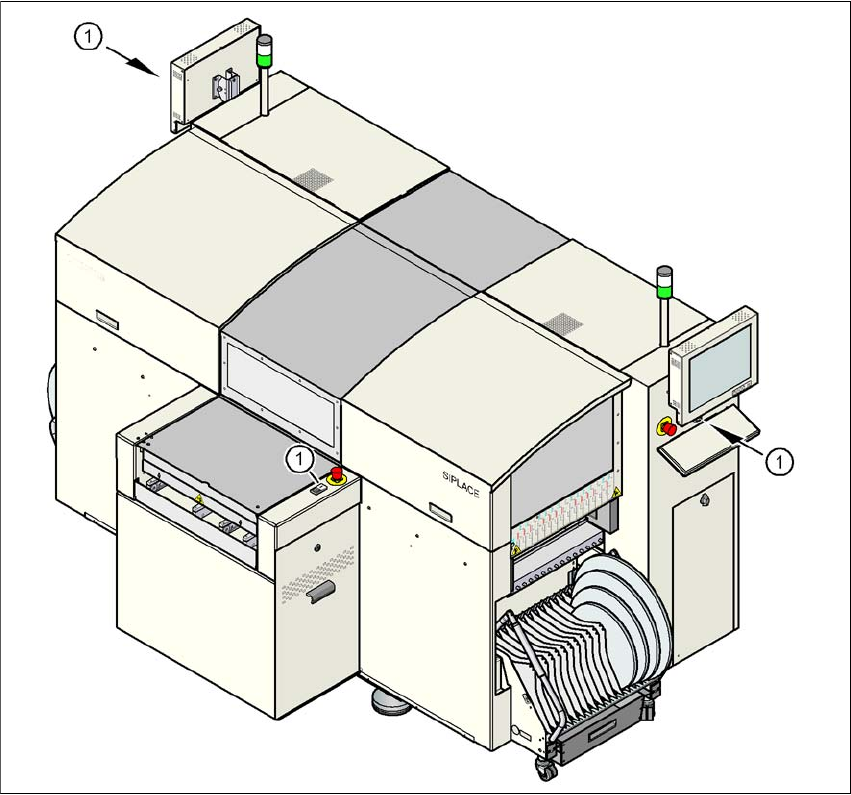
Fig. 2.6 - 3 Position of the start button (white) on the machine
(1) Start button (white) on the machine