00195741-0102_UM_D1_D2_SR605_EN.pdf - 第227页
User Manual SIPLACE D1/D2 4 Setting up and commissioning From software version SR.605.xx 07/2008 EN Edition 4.5 Adapting the used tape channel 227 4.5 Adapting the used t ape channel If feeder m odules that process co mp…
4 Setting up and commissioning User Manual SIPLACE D1/D2
4.4 Adapting the component trolley to the PCB conveyor height From software version SR.605.xx 07/2008 EN Edition
226
4
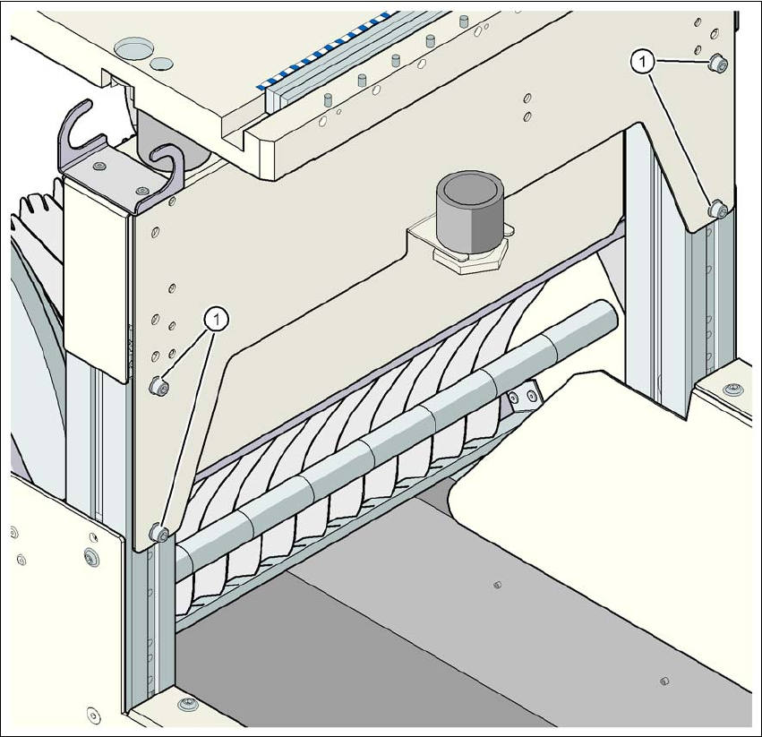
Fig. 4.4 - 9 Component trolley: PCB conveyor height 950 mm - front view, position of the hexagon socket head
screws
(1) Hexagon socket head screw M6x12 and washer (4x on the rear panel)
User Manual SIPLACE D1/D2 4 Setting up and commissioning
From software version SR.605.xx 07/2008 EN Edition 4.5 Adapting the used tape channel
227
4.5 Adapting the used tape channel
If feeder modules that process component tapes with a pocket height > 17 mm are used, such as,
for example, the 44 mm S DP feeder module, then the separating plate (item 1 in Fig. 4.5 - 1
) must
be removed.
4
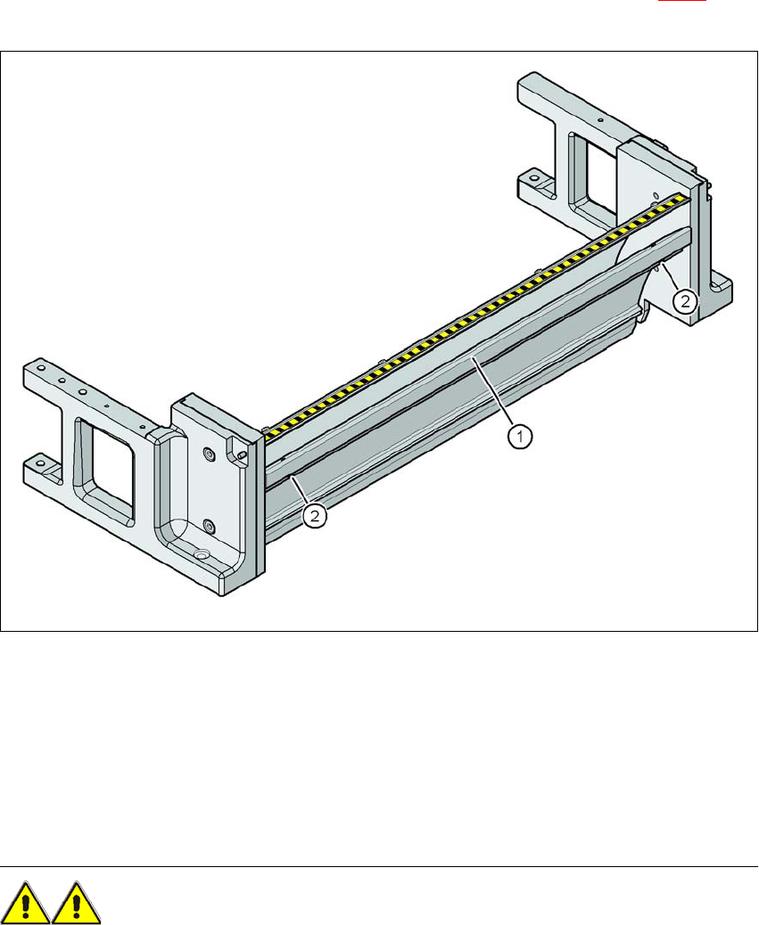
Fig. 4.5 - 1 Used tape channel with component reject bin
(1) Separating plate for tapes > 17 mm, removable
(2) DIN 84 - M3x6 screw, 2x
4
4
4.5.1 Safety instructions
WARNING 4
→ Switch the machine off at the main switch to remove the dividing plate.
→ Disconnect the machine from the power and compressed air supply.

4 Setting up and commissioning User Manual SIPLACE D1/D2
4.5 Adapting the used tape channel From software version SR.605.xx 07/2008 EN Edition
228
→ Secure the machine to prevent it being switched on again, as described in Section 2.10, page
90
.
→ Wait until the operating pressure for the tape cutter has dropped to 0 MPa.
→ Wear robust protective gloves.
→ Do not reach inside the used tape channel.
4.5.2 Removing the separating plate
→ Loosen the two slotted screws (item 2 in Fig. 4.5 - 1, page 227)
→ Pull out the separating plate (item 1 in Fig. 4.5 - 1
, page 227).