00195741-0102_UM_D1_D2_SR605_EN.pdf - 第239页
User Manual SIPLACE D1/D2 5 Tasks for the operating personnel From software version SR.605.xx 07/2008 EN Edition 5.2 Controls and displays 239 Main power switch 5 The main power switch is part of the power mod ule . It i…

5 Tasks for the operating personnel User Manual SIPLACE D1/D2
5.2 Controls and displays From software version SR.605.xx 07/2008 EN Edition
238
5.2.4 Ergonomic arrangement of the controls
Figures 5.2 - 1, page 235 and 5.2 - 2, page 236 provide an overview of the positions of the con-
trols. They are subdivided into the following groups:
Operator panel on the right-hand side (pneumatic unit) of the center console: 5
– LCD touchscreen
– Keyboard with trackball
– Start button, stop button
Operator panel on the left-hand side (power supply unit) of the center console: 5
– LCD touchscreen
– Keyboard with trackball
– Component counter
– Start button
– Stop button
– Main power switch
PCB conveyor input side: 5
– EMERGENCY STOP button
– Start button, stop button
Machine frame beneath the protective covers: 5
– Button for raising the component table for locations 1 and 2
5
5
5
5
5.2.4.1 Controls on the machine's operator panels
The two operator panel have identical control functions.
Monitor, keyboard, emergency stop button, start and stop buttons 5
There is a LCD touchscreen and a keyboard on both sides of the machine. The start and stop but-
tons are located beneath the LCD screen. The on-screen dialog will occasionally prompt you to
activate certain actions using buttons, and this arrangement will make it easier for you both to ac-
tivate and to interactively control these actions. Each operator panel has an emergency stop but-
ton to allow a fast response in an emergency.
User Manual SIPLACE D1/D2 5 Tasks for the operating personnel
From software version SR.605.xx 07/2008 EN Edition 5.2 Controls and displays
239
Main power switch 5
The main power switch is part of the power module. It is located on the left-hand operator panel
viewed in the direction of PCB transport. It is located here because it is only needed for servicing
and preventive maintenance work and is therefore not subject to frequent use.
5.2.4.2 Controls on the input side of the machine
EMERGENCY STOP buttons, start and stop buttons 5
There is an emergency stop button and start and stop buttons on the input side of the PCB con-
veyor. This arrangement was adopted for the buttons because it enables them to be reached
quickly and easily from any position.
5 Tasks for the operating personnel User Manual SIPLACE D1/D2
5.3 Note operating status indicator lamp From software version SR.605.xx 07/2008 EN Edition
240
5.3 Note operating status indicator lamp
The indicator lamp is used to signal operating statuses and malfunctions of the machine.
5.3.1 Description
5
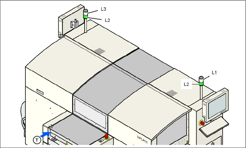
Fig. 5.3 - 1 Operating status indicator lamp
L1 Fault indicator lamp (white, right)
L2 Operating status indicator lamp (green, both lamps switched in parallel)
L3 Fault indicator lamp (white, left)
T Direction of PCB transport
5.3.2 General operating statuses
– Operating status indicator lamp L2 (green) on continuously
The machine is in service.
– Operating status indicator lamp L2 (green) flashes
The machine is waiting for a PCB on the input belt or the machine is waiting until the output
belt is free.
– Right fault indicator lamp L1 (white) flashes
One or more tracks are empty on the right-hand side of the machine. The machine populates
the current PCB with the existing components.