00195741-0102_UM_D1_D2_SR605_EN.pdf - 第203页
User Manual SIPLACE D1/D2 4 Setting up and commissioning From software version SR.605.xx 07/2008 EN Edition 4.3 Setting up the machine 203 4.3 Setting up the machine 4.3.1 PCB conveyor he ight s on the machine The machin…
4 Setting up and commissioning User Manual SIPLACE D1/D2
4.2 Infrastructure at the installation location From software version SR.605.xx 07/2008 EN Edition
202
4.2.4 Interfaces
4
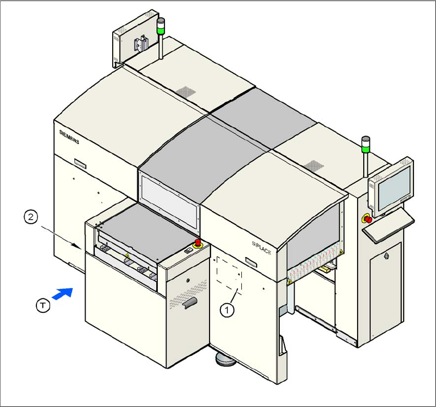
Fig. 4.2 - 10 Interfaces
4
(1) Conveyor control with Siemens conveyor interface
(2) PC and LAN connection in the "PCB input" attachment
(T) PCB transport direction
User Manual SIPLACE D1/D2 4 Setting up and commissioning
From software version SR.605.xx 07/2008 EN Edition 4.3 Setting up the machine
203
4.3 Setting up the machine
4.3.1 PCB conveyor heights on the machine
The machine can be set to the following PCB conveyor heights:
830 mm ± 15 mm Standard height 4
900 mm ± 15 mm option 4
930 mm ± 15 mm option 4
950 mm ± 15 mm SMEMA option 4
PLEASE NOTE 4
The PCB conveyor height is the distance between the top edge of the PCB conveyor belt and the
bottom edge of the machine feet.
4.3.2 Warning instructions
DANGER 4
Only SIPLACE engineers or qualified people are permitted to set up and commission the machine.
→ Always follow the applicable accident prevention regulations.
→ Never lie beneath the machine in order to attach the machine feet. All the modules and parts
can be fitted from the spaces for the component tables. If you nevertheless have to carry out
assembly work underneath the machine, then you must secure the machine by suitable
means. The fork-lift must not be used as the only support.
→ Make sure that the gantries are positioned over the PCB conveyor area so that you do not
restrict your head movement during assembly, thus excluding the risk of injury.
→ Two people will be needed to adjust the height of the machine:
– one person to carry out the necessary assembly work,
– the other person to watch the raised machine during assembly and ensure that it does not
move.
→ Wear special safety boots to protect your feet.

4 Setting up and commissioning User Manual SIPLACE D1/D2
4.3 Setting up the machine From software version SR.605.xx 07/2008 EN Edition
204
4.3.3 Tools and equipment
You will need the following tools and equipment to adjust the height of your machine:
– Single-ended spanner, size 65, item no. 00353827-01
Size 65 for the hexagon lock nut M24 on the machine foot 4
– Allen key, size 10, item no. 00373926-01
for hexagon socket head screws M12 for fixing the spacers for the machine feet 4
– Fork-lift
Fork length: min. 1800 mm 4
Carrying power: min. 3000 kg 4
Width between forks: see Fig. 4.3 - 1
, page 205 4
– Spirit level: Accuracy 0.02 mm/m
– Air cushion transport system: SIPLACE HSxx, item no. 00119002-xx