00195741-0102_UM_D1_D2_SR605_EN.pdf - 第209页
User Manual SIPLACE D1/D2 4 Setting up and commissioning From software version SR.605.xx 07/2008 EN Edition 4.3 Setting up the machine 209 4.3.7 Machine foot clear ances and the stationary PCB conveyor edges 4.3.7.1 Mach…
4 Setting up and commissioning User Manual SIPLACE D1/D2
4.3 Setting up the machine From software version SR.605.xx 07/2008 EN Edition
208
4.3.5 Fitting the indicator lamps
→ Remove both upper cover plates.
→ Connect the cables of the indicator lamps to the cables on the basic machine.
→ Insert the indicator lamp into the hole until the tube of the indicator lamp projects sufficiently
into the terminal beneath.
→ Tighten the hexagon socket head screw on the terminal.
→ Fasten both upper cover plates.
4.3.6 Fixing the monitors
→ Fix the monitors and connect the cables.
→ Check the cable connections
User Manual SIPLACE D1/D2 4 Setting up and commissioning
From software version SR.605.xx 07/2008 EN Edition 4.3 Setting up the machine
209
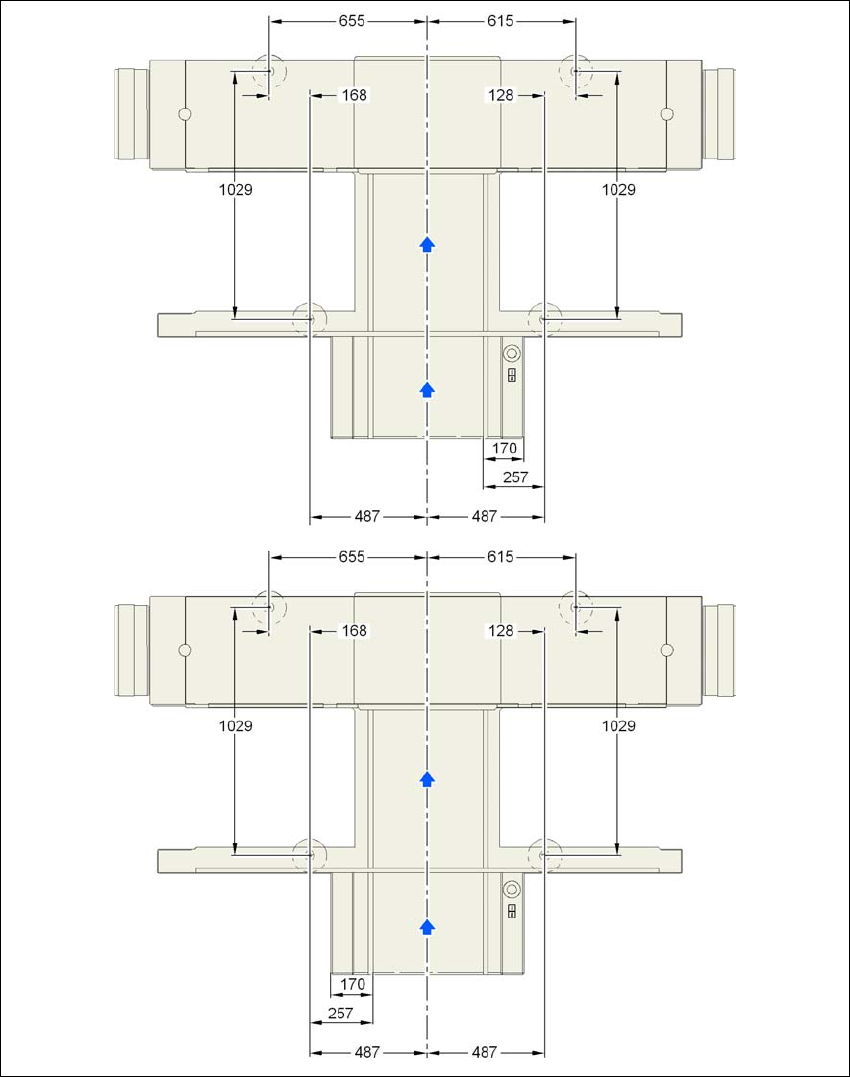
4.3.7 Machine foot clearances and the stationary PCB conveyor edges
4.3.7.1 Machine foot clearances and the stationary right and left
conveyor edge for the PCB single conveyor
4
Fig. 4.3 - 3 Machine foot clearances and the stationary right and left conveyor edge for the PCB single conveyor in
millimeters
Stationary conveyor
side right
Stationary conveyor
side left
4 Setting up and commissioning User Manual SIPLACE D1/D2
4.3 Setting up the machine From software version SR.605.xx 07/2008 EN Edition
210
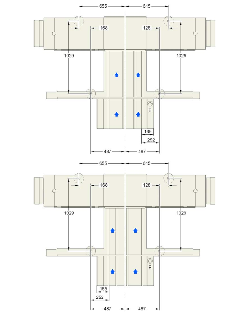
4.3.7.2 Machine foot clearances and the stationary right and left
conveyor edge for the PCB dual conveyor
4
Fig. 4.3 - 4 Machine foot clearances and the stationary right and left conveyor edge for the PCB dual conveyor in mil-
limeters
Stationary conveyor
side right
Stationary conveyor
side left