00195741-0102_UM_D1_D2_SR605_EN.pdf - 第140页
3 Technical data for the machine User Manual SIPLACE D1/D2 3.9 Vision system From software ve rsion SR.605.xx 07/2008 EN Edition 140 3.9.3 St ationary P&P component cam era, type 36, 32 x 32, digital 3.9.3.1 Structur…
User Manual SIPLACE D1/D2 3 Technical data for the machine
From software version SR.605.xx 07/2008 EN Edition 3.9 Vision system
139
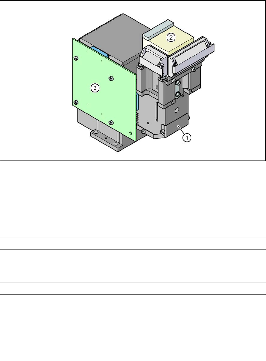
3.9.2 C&P component camera, type 29, 27 x 27, digital
3.9.2.1 Structure
3
Fig. 3.9 - 3 C&P component camera, type 29, 27 x 27, digital
(1) Component camera lens and illumination
(2) Camera amplifier
(3) Illumination control
3.9.2.2 Technical data
3
Component dimensions 0.3 x 0.3 mm² to 18.7 x 18.7 mm²
Range of components 0201 to 27 x 27 mm²
PLCC, SO, QFP, TSDP, SOT, MELF, CHIP, IC BGA
Min. lead pitch 0.3 mm
Min. lead width 0.15 mm
Min. ball pitch 0.25 mm for components < 18 x 18 mm²
0.35 mm for components ≥18 x 18 mm²
Min. ball diameter 0.14 mm for components < 18 x 18 mm²
0.2 mm for components ≥ 18 x 18 mm²
Field of vision 32 x 32 mm²
Method of illumination Front-illumination (5 levels, programmable as required)
3 Technical data for the machine User Manual SIPLACE D1/D2
3.9 Vision system From software version SR.605.xx 07/2008 EN Edition
140
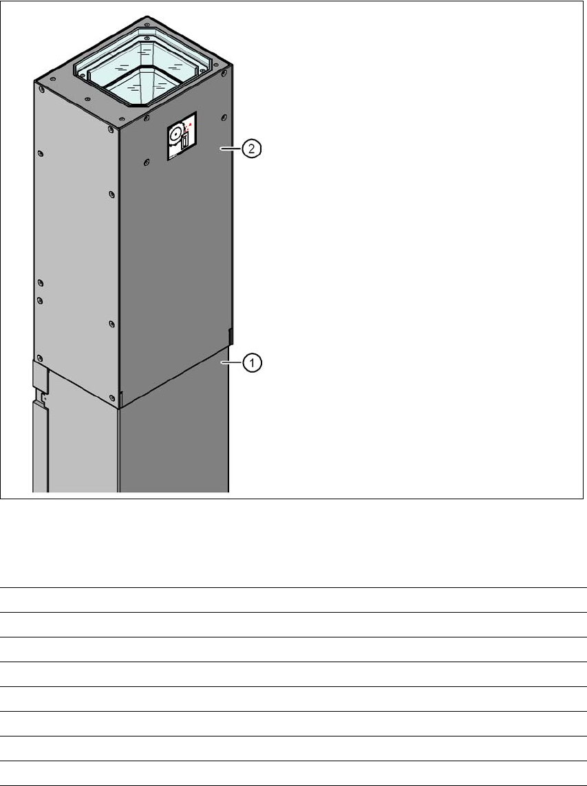
3.9.3 Stationary P&P component camera, type 36, 32 x 32, digital
3.9.3.1 Structure
3
Fig. 3.9 - 4 Structure for the stationary P&P component camera, type 36, 32 x 32, digital
3.9.3.2 Technical data
3
(1) Camera housing with integral camera
and camera amplifier
(2) Glass plate - over the illumination and
lens levels
Component dimensions 0.8 x 0.8 mm² to 32 x 32 mm² (single measurement)
Range of components 0603, MELF, SO, PLCC, QFP, electrolytic capacitors, BGA
Min. lead pitch 0.4 mm
Min. lead width 0.24 mm
Min. ball pitch 0.56 mm
Min. ball diameter 0.32 mm
Field of vision 38 x 38 mm²
Method of illumination Front-illumination (6 levels, programmable as required)
User Manual SIPLACE D1/D2 3 Technical data for the machine
From software version SR.605.xx 07/2008 EN Edition 3.9 Vision system
141
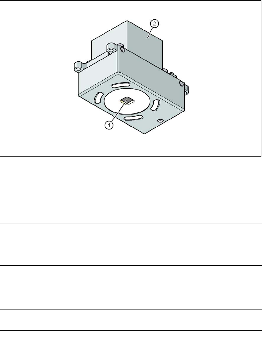
3.9.4 PCB camera, type 34, digital
3.9.4.1 Structure
3
Fig. 3.9 - 5 PCB camera, type 34, digital
(1) PCB camera lens and illumination
(2) Camera amplifier
3.9.4.2 Technical data
3
PCB fiducials Up to 3 (subpanels and multiple panels),
up to 6 for the Long board option (optional PCB fiducials are
output by the optimization).
Local fiducials Up to 2 per PCB (may be of different type)
Library memory Up to 255 fiducial types per subpanel
Image analysis Edge detection method (Singular feature) based on grayscale
values
Method of illumination Front-illumination (3 levels, programmable as required)
Detection time per fiducial
/Bad fiducial
20 ms - 200 ms
Field of vision 5.78 x 5.78 mm²
Distance from the focus plane 28 mm