00195741-0102_UM_D1_D2_SR605_EN.pdf - 第120页
3 Technical data for the machine User Manual SIPLACE D1/D2 3.6 Placement head From software version SR.605.xx 07/2008 EN Edition 120 nents are picked up by the plac ement head, optically cent ered on the way to th e plac…
User Manual SIPLACE D1/D2 3 Technical data for the machine
From software version SR.605.xx 07/2008 EN Edition 3.6 Placement head
119
3.6.3 SIPLACE Pick&Place head for high-precision IC placement
Item no. 00119833-xx SIPLACE Pick&Place head, D-series
3
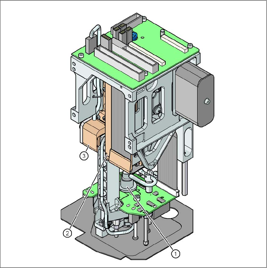
Fig. 3.6 - 5 Pick&Place head for high-precision IC placement
(1) DP axis
(2) Z axis drive
(3) Incremental distance measuring system for the Z axis
3.6.3.1 Description
This highly sophisticated placement head works on the Pick&Place principle. The SIPLACE
Pick&Place head is suitable for processing particularly difficult or large components. The compo-
3 Technical data for the machine User Manual SIPLACE D1/D2
3.6 Placement head From software version SR.605.xx 07/2008 EN Edition
120
nents are picked up by the placement head, optically centered on the way to the placement posi-
tion and rotated into the necessary placement angle. They are then placed gently and accurately
onto the PCB with a controlled blast of air.
The standard nozzles for the Pick&Place head are the type 5xx nozzles. It is also possible to fit
an adapter and then use type 4xx nozzles and type 8xx and 9xx nozzles for the Collect&Place
heads.
3.6.3.2 Technical data
3
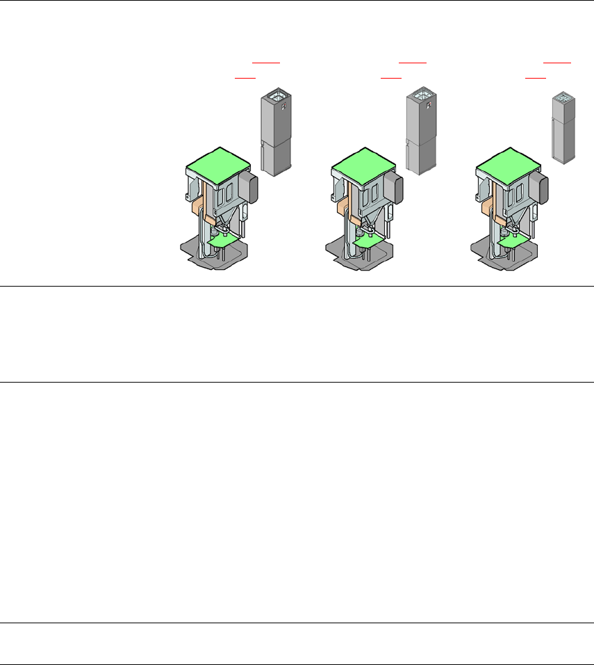
Pick&Place head
Fine-pitch camera
CO camera type 36
(see Section 3.9.3
,
page 140
)
Pick&Place head
Fine-pitch camera
CO camera type 33
(see Section 6.3.2
,
page 287
)
Pick&Place head
Flip-chip camera
CO camera type 25
(see Section 6.3.1
,
page 285
)
Range of components
a
0603 to SO, PLCC,
QFP, BGA, special
components, bare dies,
flip-chips
0402 to SO, PLCC,
QFP, BGA, special
components, bare dies,
flip-chips
0201 to SO, PLCC,
QFP, sockets, plugs,
BGA, special compo-
nents, bare dies, flip-
chips, shields
Component specification
Max. height
Min. lead pitch
Min. lead width
Min. ball pitch
Min. ball diameter
Min. dimensions
Max. dimensions
Max. weight
b
19 mm
0.4 mm
0.24 mm
0.56 mm
0.32 mm
1.6 x 0.8 mm²
32 x 32 mm²
(single measurement)
85 x 85 mm² or
max. 200 x 125 mm²
(with restrictions)
100 g
19 mm
0.3 mm
0.15 mm
0.35 mm
0.2 mm
1.0 x 0.5 mm²
55 x 45 mm²
(single measurement)
85 x 85 mm² or
max. 200 x 125 mm²
(with restrictions)
100 g
19 mm
0.25 mm
0.1 mm
0.14 mm
0.08 mm
0.6 x 0.3 mm²
16 x 16 mm²
(single measurement)
100 g
Programmable set-down
force 1.0 N - 15 N 1.0 N - 15 N 1.0 N - 15 N

User Manual SIPLACE D1/D2 3 Technical data for the machine
From software version SR.605.xx 07/2008 EN Edition 3.6 Placement head
121
Nozzle types 5xx (standard)
4xx + adapter
8xx + adapter
9xx + adapter
5xx (standard)
4xx + adapter
8xx + adapter
9xx + adapter
5xx (standard)
4xx + adapter
8xx + adapter
9xx + adapter
X/Y accuracy
c
± 37.5 µm/3σ
± 50 µm/4σ
± 37.5 µm/3σ
± 50 µm/4σ
± 30 µm/3σ
± 40 µm/4σ
Angular accuracy ± 0.053°/3σ
± 0.071°/4σ
± 0.053°/3σ
± 0.071°/4σ
± 0.053°/3σ
± 0.071°/4σ
Component range 99.8% 99.9% 99.8%
Component camera type 36 33 25
Illumination levels 6 6 6
Possible illumination level
settings
256
6
256
6
256
6
a) Please note that the range of components that can be placed is also affected by the pad geometry, customer-spe-
cific standards, component packaging tolerances and component tolerances.
b) If standard nozzles are used
c) The accuracy value was measured using the vendor-neutral IPC standard