00195741-0102_UM_D1_D2_SR605_EN.pdf - 第77页
User Manual SIPLACE D1/D2 2 Operational safety From software version SR.605.xx 07/2008 EN Edition 2.6 Safety equipment 77 2.6.4 EMERGENCY STOP l oop and signaling circuit 2.6.4.1 Structure of the EMERGENCY ST OP loop The…

2 Operational safety User Manual SIPLACE D1/D2
2.6 Safety equipment From software version SR.605.xx 07/2008 EN Edition
76
Protective contactor combination 3TK2825 (item 1 in Fig. 2.6 - 8) 2
The protective contactor combination is contained in the power supply unit. It is used to monitor
the EMERGENCY STOP circuits and safety equipment.
There are three conditions that must be fulfilled in order to activate the protective contactor com-
bination:
– The "software enable" signal must have been sent.
– The EMERGENCY STOP loop must be closed.
– The start button must have been pressed.
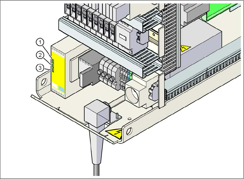
On the front panel of the protective contactor combination, there are three green operating display
LEDs (see Fig. 2.6 - 9
, page 77):
– The "Power" LED indicates that voltage is present.
– The "Channel 1" and "Channel 2" LEDs light up if the start button was pressed, the EMER-
GENCY STOP loop is closed and the signaling circuit is not signaling a fault status.
Service socket (item 4 in Fig. 2.6 - 8, page 72) 2
The service socket is contained in the power supply unit and is protected by the cover. It can only
be used if the machine is connected to the main power supply via a 5-wire connection (U, V, W,
N, and PE). If a 4-wire connection is used, e.g. without N, the socket cannot be used.
WARNING 2
Always follow the safety instructions concerning potentially lethal voltages - even when the
machine is switched off (see Section 2.6.2.4 from page 73).
User Manual SIPLACE D1/D2 2 Operational safety
From software version SR.605.xx 07/2008 EN Edition 2.6 Safety equipment
77
2.6.4 EMERGENCY STOP loop and signaling circuit
2.6.4.1 Structure of the EMERGENCY STOP loop
The following contacts are connected in series and form the EMERGENCY STOP loop:
– normally open (NO) contacts for the two protective cover switches
– normally open (NO) contacts in the two protective switches for the cover flaps over the PCB
conveyor
– normally open (NO) contacts for the two EMERGENCY STOP buttons
– normally open (NO) contacts for the two component trolleys
– channels 2 and 3 of the protective contactor combination K1
If the EMERGENCY STOP loop is closed, 24 VDC is present at channels 2 and 3 of the PCC.
The two green LEDs for channels 2 and 3 light up in addition to the green Power ON LED.2
2
Fig. 2.6 - 9 Signal LED on the protective contactor combination
(1) Power
(2) Channel 1
(3) Channel 2
2 Operational safety User Manual SIPLACE D1/D2
2.6 Safety equipment From software version SR.605.xx 07/2008 EN Edition
78
2.6.4.2 Structure of the signaling circuit
The four signaling contacts for the protective covers and cover flaps are connected in parallel and
form the "cover signal" circuit. If one or more protective covers or cover flaps are opened, the con-
tacts close, and the 24 V signal reaches the CAN bus and signals that one of the covers or flaps
is open.
The three signaling contacts for the emergency stop buttons are connected in parallel and form
the "emergency stop button signal circuit". When an EMERGENCY STOP button is pressed, a
24 V signal is sent to the CAN bus and signals that one of the EMERGENCY STOP buttons has
been pressed.
The two signaling contacts for the component trolleys are connected in series and form the "Com-
ponent table" signal loop. If a component trolley is missing, a 0 V signal is sent to the CAN bus. If
all trolleys are connected, the signal is approximately 16 V.
2.6.4.3 Description of the functions of the EMERGENCY STOP loop
The following conditions must be fulfilled before the machine can be started or operated:
– Both component trolleys must be docked in and connected.
– All protective covers must be closed.
– Both cover flaps over the PCB conveyor must be closed.
– The three EMERGENCY STOP buttons must be released.
– The minimum operating pressure must have been reached.
– The "software enable" signal must be active. This ensures that the EMERGENCY STOP loop
is closed.
– The power supply must be sending 24 V to the start buttons and the protective contactor com-
bination.
– If one of the start buttons is now pressed, the protective contactor combination PCC will
switch and activate the following components:
– 200 V link voltage for the servo amplifiers for the gantry axes
– 150 V link voltage for the star axes
– The axis unit will receive a "Servo Enable" signal for the servo amplifier.
– 24 V operating voltage is switched to the used tape cutters.
– The 40 V operating voltage is switched through to the PCB conveyor for the belt motors.
– The PCB conveyor control receives the enable signal for the PCB clamping, the PCB
stopper and the lifting table control.
The machine is then ready for use.