00195741-0102_UM_D1_D2_SR605_EN.pdf - 第267页
User Manual SIPLACE D1/D2 6 Station extensions From software version SR.605.xx 07/2008 EN Edition 6.1 Nozzle changer 267 6.1.1.7 Changing the magazine → T o remove the mag azine, push the spring hoo k (item 1 in Fig. 6.1…

6 Station extensions User Manual SIPLACE D1/D2
6.1 Nozzle changer From software version SR.605.xx 07/2008 EN Edition
266
CAUTION 6
Before you fill magazine, make sure that all the nozzles on the Collect&Place head have been
returned to their magazines. 6
→ Programming the nozzle changer is described in the SIPLACE Pro user manual.
PLEASE NOTE 6
→ Do not allow components to drop onto the magazines. If they do, they could jam the locking
plate.
→ Do not allow components to drop onto free feeder module locations. They will stick to the
magnetic bar. Production may have to be interrupted if the feeder modules are not placed on
the component table correctly. You should therefore regularly clean the magazines and free
locations.
6
6
6
User Manual SIPLACE D1/D2 6 Station extensions
From software version SR.605.xx 07/2008 EN Edition 6.1 Nozzle changer
267
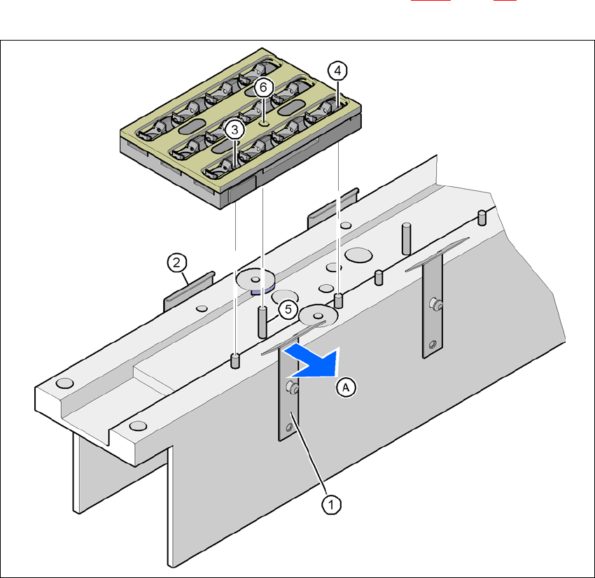
6.1.1.7 Changing the magazine
→ To remove the magazine, push the spring hook (item 1 in Fig. 6.1 - 5, page 267) away from
the magazine. Lift the magazine out of the carrier.
6
Fig. 6.1 - 5 Changing the magazine
(1) Spring hook
(2) Retaining clamp
(3) Centering hole
(4) Slot
(5) Parallel pin of the slide mechanism
(6) Hole for the parallel pin of the slide mechanism
(A) Push the spring hook away from the magazine
6
6
6 Station extensions User Manual SIPLACE D1/D2
6.1 Nozzle changer From software version SR.605.xx 07/2008 EN Edition
268
PLEASE NOTE 6
Not the following points when you insert the magazine:
→ The centering pins slide into the centering hole (item 3 in Fig. 6.1 - 5
, page 267) and into the
slot (item 4 in Fig. 6.1 - 5
, page 267).
→ The parallel pin of the slide mechanism (item 5 in Fig. 6.1 - 5
, page 267) slides into the hole
(item 6 in Fig. 6.1 - 5, page 267) in the magazine.
→ First place the side of the magazine with the numbered nozzles 1, 2, 3 and 4 on the base.
The retaining clamp (item 2 in Fig. 6.1 - 5
, page 267) must slide into the slot in the magazine.
→ Push the spring hook away from the magazine (item A in Fig. 6.1 - 5
, page 267).
→ Press the magazine so that it lies flat on the base, then release the spring hook (item 1 in Fig.
6.1 - 5
, page 267). The spring hook must latch into place.
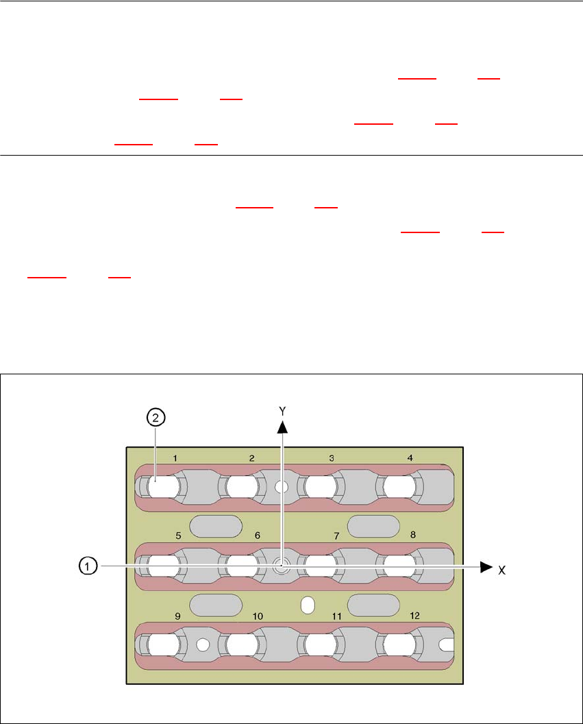
6.1.1.8 Position detection
Every magazine of the nozzle changer has a positioning fiducial for position detection.
6
Fig. 6.1 - 6 Nozzle changer - Position detection
(1) Positioning fiducial
(2) Position of the nozzles in the magazine relative to the positioning fiducial