00195741-0102_UM_D1_D2_SR605_EN.pdf - 第111页
User Manual SIPLACE D1/D2 3 Technical data for the machine From software version SR.605.xx 07/2008 EN Edition 3.6 Placement head 111 3.6 Placement head 3.6.1 12-segment Collect&Place head for high-speed placement Ite…
3 Technical data for the machine User Manual SIPLACE D1/D2
3.5 Overviews of the modules From software version SR.605.xx 07/2008 EN Edition
110
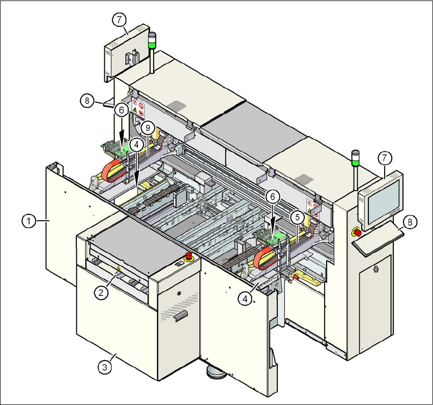
3.5.2 Overview of the modules SIPLACE D2
3
Fig. 3.5 - 2 Overview of the modules SIPLACE D2
(1) Machine frame
(2) PCB conveyor (flexible dual conveyor)
(3) extension kit
(4) Tape cutter, used tape channel (2x)
(5) Gantry 1
(6) C&P head
(7) Monitor (2x)
(8) Keyboard (2x)
(9) Gantry 2
User Manual SIPLACE D1/D2 3 Technical data for the machine
From software version SR.605.xx 07/2008 EN Edition 3.6 Placement head
111
3.6 Placement head
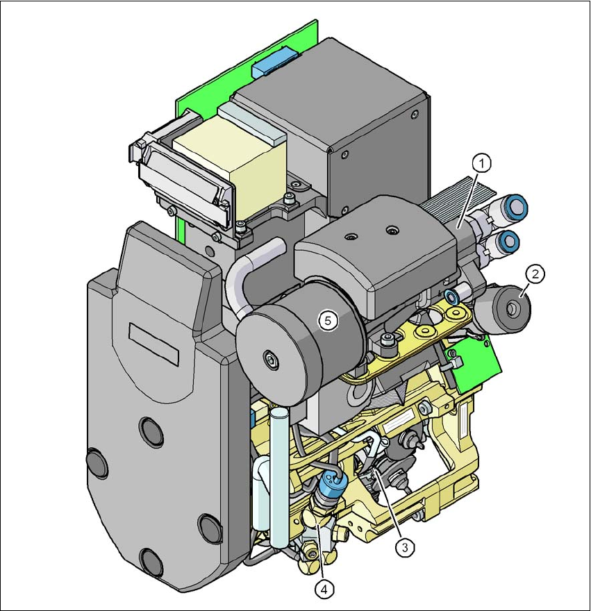
3.6.1 12-segment Collect&Place head for high-speed placement
Item no. 00119876-xx, SIPLACE 12 C&P head, D-series
3
Fig. 3.6 - 1 12-segment Collect&Place head - Function groups, part 1
3
(1) Vacuum generator
(2) Turning station, DP axis
(3) Star with 12 sleeves, star axis
(4) Forced air valve
(5) Silencer
3 Technical data for the machine User Manual SIPLACE D1/D2
3.6 Placement head From software version SR.605.xx 07/2008 EN Edition
112
3
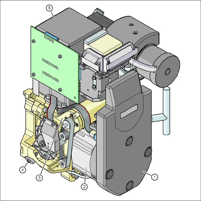
Fig. 3.6 - 2 12-segment Collect&Place head - Function groups, part 2
3
(1) Intermediate distributor board (beneath the cover)
(2) Star drive - DR motor
(3) Z axis motor
(4) Valve adjustment drive
(5) C&P component camera
3.6.1.1 Description
The 12-segment Collect&Place head works on the Collect&Place principle. This means that, with-
in each cycle, twelve components are picked up by the placement head, are optically centered on
the way to the placement position and are rotated into the required placement angle. They are