00195741-0102_UM_D1_D2_SR605_EN.pdf - 第206页
4 Setting up and commissioning User Manual SIPLACE D1/D2 4.3 Setting up the machine From software version SR.605.xx 07/2008 EN Edition 206 → With the fork-lift, raise the machine approximately 35 cm. The machine st ands …
User Manual SIPLACE D1/D2 4 Setting up and commissioning
From software version SR.605.xx 07/2008 EN Edition 4.3 Setting up the machine
205
4.3.4 Presetting the PCB conveyor height
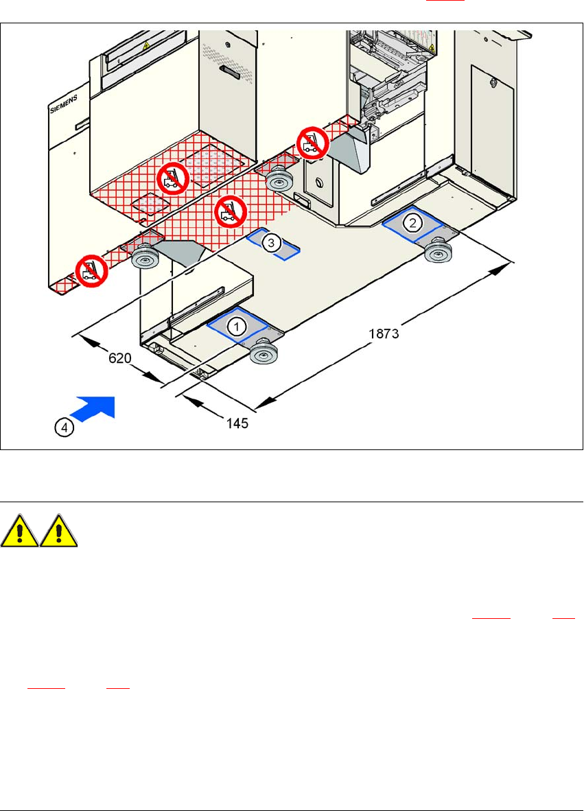
→ Push the forks of the fork-lift under the machine, as shown in Fig. 4.3 - 1.
4
Fig. 4.3 - 1 Machine's contact surface for the fork-lift - dimensions in millimeters
WARNING 4
Please note the following points before you raise the machine in order to avoid irreversible dam-
age to the machine:
→ Attach the fork-lift on the power supply side of the machine (item 4 in Fig. 4.3 - 1
, page 205).
→ Make sure that the machine attachment surfaces 1, 2 and 3 lie evenly on the fork (see Fig.
4.3 - 1
, page 205). Use wooden planks of appropriate length for support, if the fork is shorter.
→ Make sure that the forks are evenly loaded when you lift the machine. A firm support between
the forks and machine will prevent the machine tilting when it is raised. This will also prevent
a one-sided load on the machine feet, which would deform the fixing of the machine feet. We
recommend that a second person watch the machine as it is raised, and make sure that the
machine does not tip to one side when lifted with the fork-lift.
4 Setting up and commissioning User Manual SIPLACE D1/D2
4.3 Setting up the machine From software version SR.605.xx 07/2008 EN Edition
206
→ With the fork-lift, raise the machine approximately 35 cm.
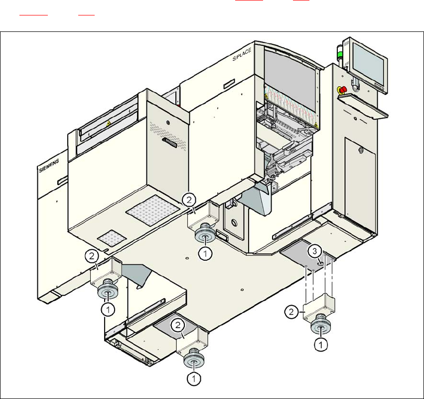
The machine stands on 4 machine feet (item 1 in Fig. 4.3 - 2
, page 206) with 4 spacers (item 2 in
Fig. 4.3 - 2
, page 206) for adjusting the height, if necessary.
4
Fig. 4.3 - 2 Machine feet
(1) Machine foot, 4x
(2) Machine foot, 4x
(3) Hole in the machine frame for the machine foot for the 830 mm PCB conveyor height

User Manual SIPLACE D1/D2 4 Setting up and commissioning
From software version SR.605.xx 07/2008 EN Edition 4.3 Setting up the machine
207
4.3.4.1 Spacers for the PCB conveyor heights of 900 / 930 / 950 mm
There are different spacers (see item 2 in Fig. 4.3 - 2) and fixing screws for the 900 / 930 / 950
mm PCB conveyor height. You will need 4 spacers and 16 fixing screws.
4.3.4.2 Presetting the PCB conveyor height to 830 mm
You will not need a spacer for a PCB conveyor height of 830 mm.
→ Insert the machine feet into the holes in the machine frame (item 4 in Fig. 4.3 - 2
, page 206).
→ Use the M24 nuts to set the height of the machine feet (item 1 in Fig. 4.3 - 2
, page 206) so
that the distance between the underside of the machine foot and the bottom edge of the ma-
chine frame is 115 mm.
→ Hand-tighten the M24 nuts.
4.3.4.3 Presetting the PCB conveyor height to 900 / 930 / 950 mm
→ Then fix the 4 spacers (item 2 in Fig. 4.3 - 2, page 206).
The spacers for the different PCB conveyor heights are listed in Section 4.3.4.1
, page 207.
→ Use the M24 nuts to set the height of the machine feet (item 1 in Fig. 4.3 - 2
, page 206) to the
following values:
PCB conveyor
height
Spacer, 4x
Item no.
Spacer
Height
Hexagon socket
head screw, 16x
830 mm – – –
900 mm 00344069-xx 70 mm DIN 912 M12x70
930 mm 00344070-xx 100 mm DIN 912 M12x100
950 mm 00331553-xx 122.5 mm DIN 912 M12x100
PCB conveyor height Distance from underside of machine foot to bottom
edge of machine frame
900 mm 185 mm
930 mm 215 mm
950 mm 237 mm