00195741-0102_UM_D1_D2_SR605_EN.pdf - 第21页
User Manual SIPLACE D1/D2 1 Introduction From software version SR.605.xx 07/2008 EN Edition 1.1 Description of the machine 21 – 0 201 packa ge We can supply the 0 201 package for processing 0201 component s with the 12-s…
1 Introduction User Manual SIPLACE D1/D2
1.1 Description of the machine From software version SR.605.xx 07/2008 EN Edition
20
1
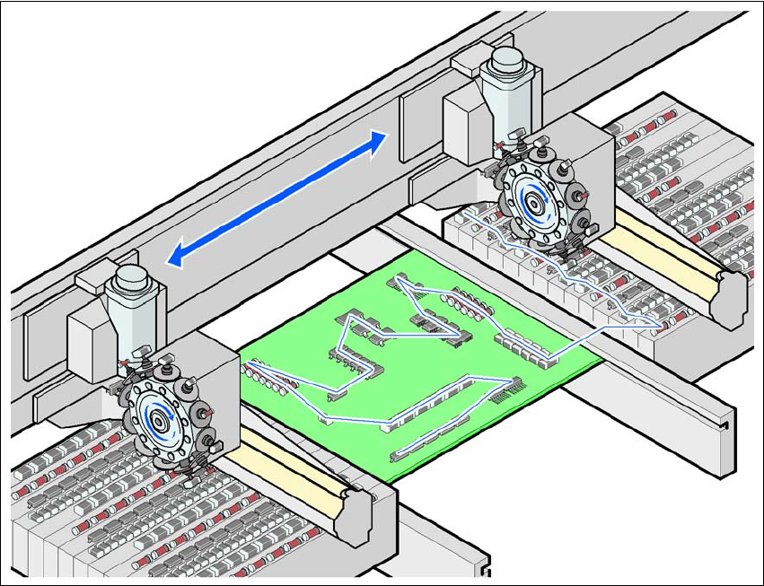
Fig. 1.1 - 3 The SIPLACE principle
1.1.5 New options and performance features
The following options are available to extend the machines' functionality:
– 01005 package
The SIPLACE D1 and D2 placement machines are prepared to place 01005 components as
standard. For placement simply retrofitting of the 12 segment Collect&Place head with the
01005 package is necessary. 1
– 01005 tape feeder module
The tape feeder module specially developed for 01005 components makes components
available of the sizes 01005 to 0402. 1
– 3x8mm SL tape feeder module
SL means shutterless, that is without a component cover. Dispensing with unnecessary me-
chanical parts reduces the procurement and maintenance costs for this feeder module. 1
User Manual SIPLACE D1/D2 1 Introduction
From software version SR.605.xx 07/2008 EN Edition 1.1 Description of the machine
21
– 0201 package
We can supply the 0201 package for processing 0201 components with the 12-segment Col-
lect&Place head. 1
– Stationary component camera, type 33
Use component camera , type 33, with the higher resolution and the larger field of view in
place of component camera type 36. 1
– Single head configuration
The SIPLACE D1 placement machine can be configured as single head machine.
– Splice detection for tape feeder modules
Splice detection for tape feeder modules can be retrofitted on the machines.
1 Introduction User Manual SIPLACE D1/D2
1.1 Description of the machine From software version SR.605.xx 07/2008 EN Edition
22
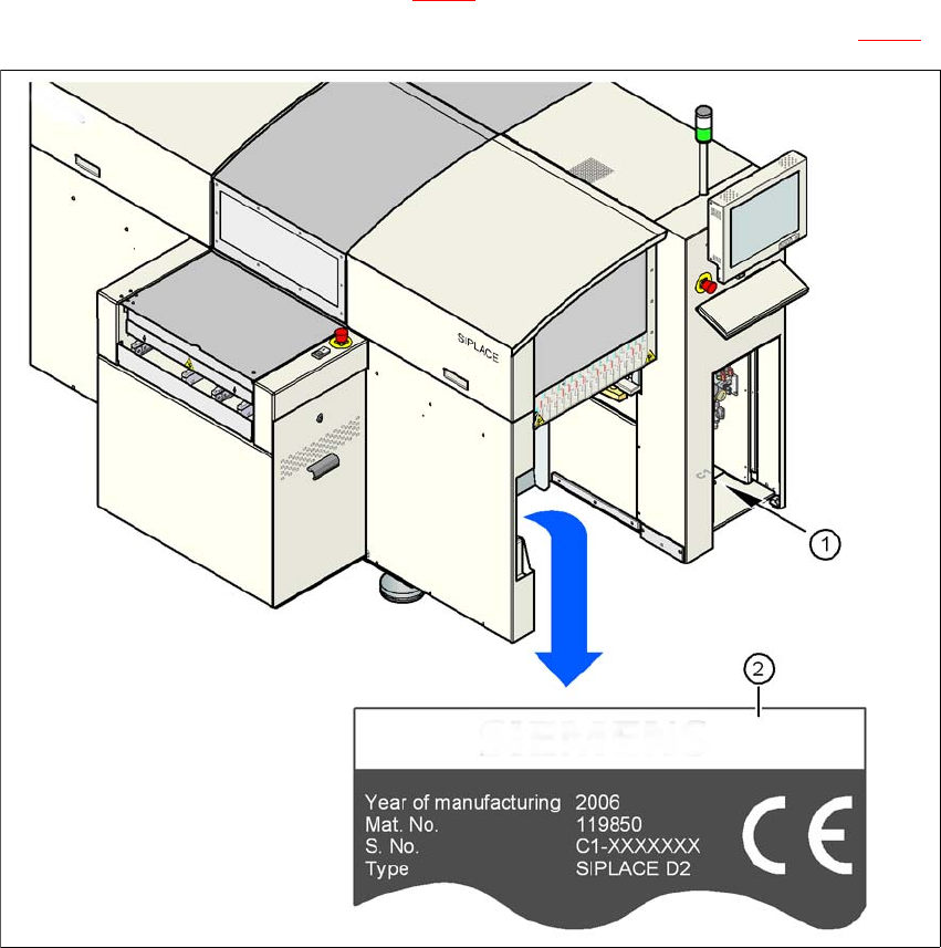
1.1.6 Serial number of the machine
The serial number of the machine can be found in two different places.
– The serial number (e.g. C1) is struck on the base of the machine frame, on the same side as
the pneumatic unit (see item 1 in Fig. 1.1 - 4
).
– The serial number is also punched on the machine's rating plate (see item 2 in Fig. 1.1 - 4
).
1
Fig. 1.1 - 4 Places with the serial number on the machine