00195741-0102_UM_D1_D2_SR605_EN.pdf - 第136页
3 Technical data for the machine User Manual SIPLACE D1/D2 3.8 PCB conveyor system From software version SR.605.xx 07/2008 EN Edition 136 PCB warpage do wn, max. 0.5 mm 3 → Use magnetic pin sup ports to achieve this valu…
User Manual SIPLACE D1/D2 3 Technical data for the machine
From software version SR.605.xx 07/2008 EN Edition 3.8 PCB conveyor system
135
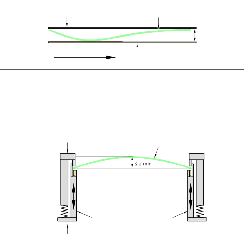
PCB warpage in direction of travel + PCB thickness < 5.5 mm
3
3
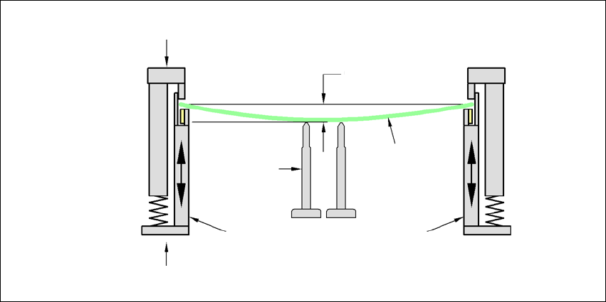
3.8.8.2 PCB warpage during placement
A warpage of 2 mm can lead to problems focusing on local fiducials and ink spots in the middle of
the PCB. The digital camera's focus is 2 mm. When all the tolerances are taken into account, this
value is reduced to 1.5 mm. Also note that the component height is reduced by the warpage.
3
3
Fixed clamped edge
Conveyor belt
Printed circuit board
PCB transport direc-
tion
5.5 mm
Movable clamping device
Fixed clamped edge
Printed circuit board
Conveyor rail
3 Technical data for the machine User Manual SIPLACE D1/D2
3.8 PCB conveyor system From software version SR.605.xx 07/2008 EN Edition
136
PCB warpage down, max. 0.5 mm
3
→ Use magnetic pin supports to achieve this value.
Printed circuit board
Magnetic pin
support
Movable clamping device
Fixed clamped edge
Conveyor rail
0.5 mm
User Manual SIPLACE D1/D2 3 Technical data for the machine
From software version SR.605.xx 07/2008 EN Edition 3.9 Vision system
137
3.9 Vision system
A component camera is integrated into each Collect&Place head (see Fig. 3.6 - 2 page 112 and
3.6 - 4
page 116).
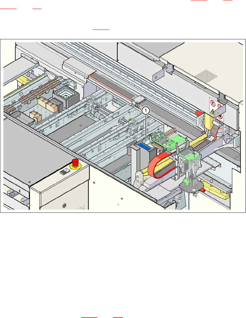
On the D1 machine, the stationary component camera, type 36, for the Pick&Place head is fixed
to the machine frame (item 1 in Fig. 3.9 - 1
).
3
Fig. 3.9 - 1 D1 machine: assembly positions for the stationary component camera, type 36
The component vision module is used to determine:
– the precise position of the components at the nozzle and
– the geometry of the package form.
The PCB vision module uses fiducials on the PCBs to determine:
– the position of the PCB,
– its rotation angle
– and the PCB skew.
The PCB camera (item 2 in Fig. 3.9 - 5
page 141 is fixed to the underside of the gantry. They use
fiducials on the feeder modules to determine the exact pick-up position of components, which is
particularly important for small components.