00195741-0102_UM_D1_D2_SR605_EN.pdf - 第130页
3 Technical data for the machine User Manual SIPLACE D1/D2 3.8 PCB conveyor system From software version SR.605.xx 07/2008 EN Edition 130 throughout the plac ement operation. The placem ent sequence star ts as soon as a …
User Manual SIPLACE D1/D2 3 Technical data for the machine
From software version SR.605.xx 07/2008 EN Edition 3.8 PCB conveyor system
129
3
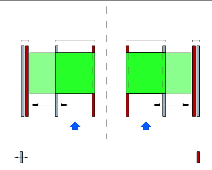
Fig. 3.8 - 3 Flexible dual conveyor in Single conveyor mode
3.8.3.5 Transport modes
The flexible dual conveyor can be used in two modes:
– Synchronous transport mode
– Asynchronous transport mode
3.8.3.6 Asynchronous transport mode
Description 3
In asynchronous mode, only one PCB in a transport track is processed. At the same time, another
PCB in the second transport track is moved into the placement position. This saves the full con-
veying time of one PCB, thus considerably increasing performance, particularly for PCBs with a
short cycle time.
Once the machine has received the job data (panel, set-up), the PCBs on the feeding belts are
continuously transported to the available processing belt (provided that the processing belt is free)
Dual conveyor with widened conveyor track 2
(stationary conveyor side wall on left)
Conveyor track 2
deactivated
Conveyor track 1 Conveyor track 2 Conveyor track 1
deactivated
PCB transport direction PCB transport direction
Stationary conveyor side wall
Dual conveyor with widened conveyor track 1
(stationary conveyor side wall on right)
Movable conveyor side wall
3 Technical data for the machine User Manual SIPLACE D1/D2
3.8 PCB conveyor system From software version SR.605.xx 07/2008 EN Edition
130
throughout the placement operation. The placement sequence starts as soon as a PCB has
moved onto the processing belt. The PCBs are processed one after another.
If the placement sequence is interrupted, the conveyor interface will be disabled and the PCBs
currently on the processing belts will be completed.
The conveyor interface is disabled or enabled simultaneously for both transport tracks.
3
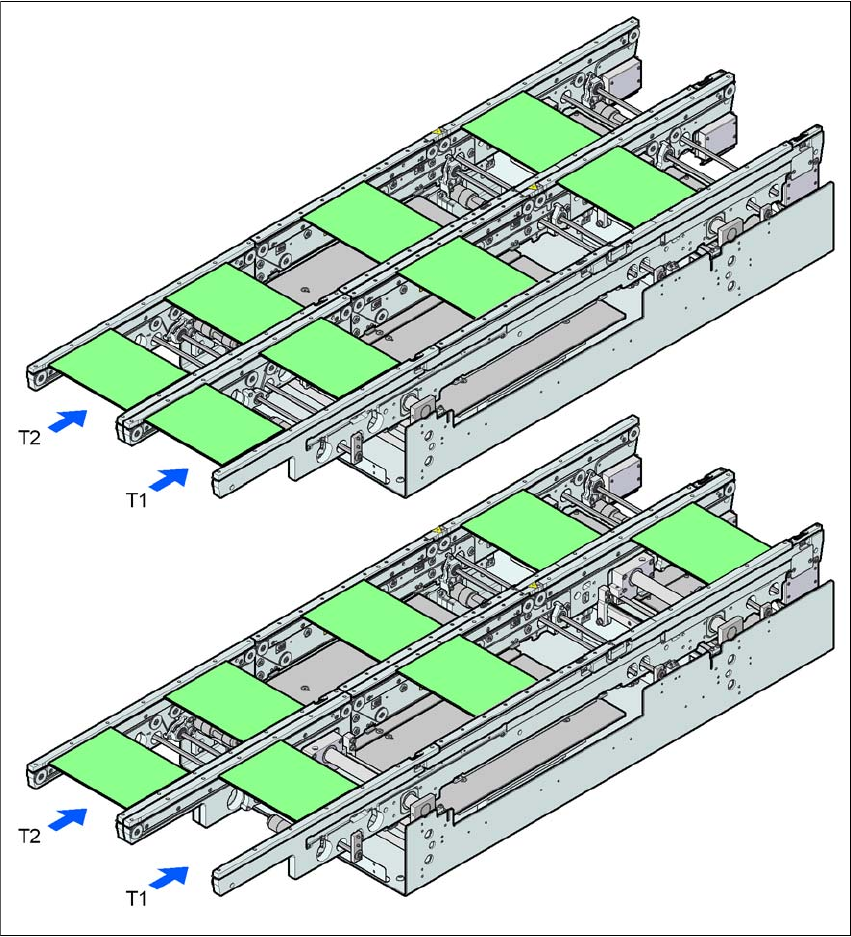
Fig. 3.8 - 4 Transport modes
Synchronous transport mode
Asynchronous transport mode
User Manual SIPLACE D1/D2 3 Technical data for the machine
From software version SR.605.xx 07/2008 EN Edition 3.8 PCB conveyor system
131
3.8.3.7 Synchronous transport mode
Description 3
In synchronous mode, two PCBs of the same size are moved into the placement position at the
same time. They must be processed as a common panel.
In this way, the top and bottom of a PCB can be processed on a single line, and the time required
to transport the PCB is shorter since two PCBs are always transported at the same time. It also
ensures better utilization of the nozzle configuration.
PCBs on conveyor tracks 1 and 2 are moved synchronously onto the conveyor sections (i.e. the
conveyors are controlled synchronously, but independently of one another). The components to
be placed on conveyor tracks 1 and 2 must be organized into a panel via two subpanels. (See the
SIPLACE Pro user manual).
If only one conveyor track is full when the placement sequence starts, the subpanel on this section
will be identified as “not for placement”.
If the dual conveyor is operated in synchronous mode, the ‘PCB whispering down the line’ option
is deactivated. PCB barcode operation is not supported in this mode. The "Global bad fiducial"
option cannot be used.
3
3.8.4 Controlling and width adjustment
3.8.4.1 Controlling using the Single Functions menu
The online help contains information on controlling the PCB dual conveyor system and on the sin-
gle functions menu.
3.8.4.2 Automatic width adjustment
When the command is received, the conveyors are set to the desired width one after another. Dif-
ferent widths are possible.
See the online help for detailed information about changing the conveyor track width.