00195741-0102_UM_D1_D2_SR605_EN.pdf - 第264页
6 Station extensions User Manual SIPLACE D1/D2 6.1 Nozzle changer From software version SR.605.xx 07/2008 EN Edition 264 6.1.1.4 Position of the nozzle changers for t he C&P12 head on the D2 machine A nozzle changer …
User Manual SIPLACE D1/D2 6 Station extensions
From software version SR.605.xx 07/2008 EN Edition 6.1 Nozzle changer
263
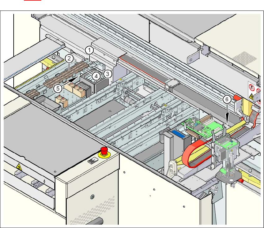
6.1.1.3 Position of the nozzle changer for the C&P12 head on the D1 machine
One nozzle changer for the 12-segment Collect&Place head may be installed at location 2 (item
1 in Fig. 6.1 - 2
). This gives a total capacity of 6 magazines with a total of 72 nozzle holders.
6
Fig. 6.1 - 2 Position of the nozzle changer for the 12-segment Collect&Place head on the D1 machine
6
(1) Nozzle changer
(2) Nozzle magazine
(3) Take-off device for nozzles, type 8xx
(4) Take-off device for nozzles, type 9xx
(5) Reject bin for nozzles
(6) Reject bin for components
6 Station extensions User Manual SIPLACE D1/D2
6.1 Nozzle changer From software version SR.605.xx 07/2008 EN Edition
264
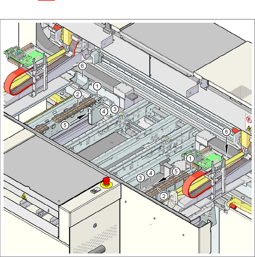
6.1.1.4 Position of the nozzle changers for the C&P12 head on the D2 machine
A nozzle changer for the 12-segment Collect&Place head may be installed at locations 1 and 2
(item 1 in Fig. 6.1 - 2
). This gives a total capacity of 2 nozzle changers with 12 magazines and a
total of 144 nozzle holders.
6
Fig. 6.1 - 3 Position of the nozzle changer for the 12-segment Collect&Place head on the D2 machine
6
(1) Nozzle changer
(2) Nozzle magazine
(3) Take-off device for nozzles, type 8xx
(4) Take-off device for nozzles, type 9xx
(5) Reject bin for nozzles
(6) Reject bin for components
User Manual SIPLACE D1/D2 6 Station extensions
From software version SR.605.xx 07/2008 EN Edition 6.1 Nozzle changer
265
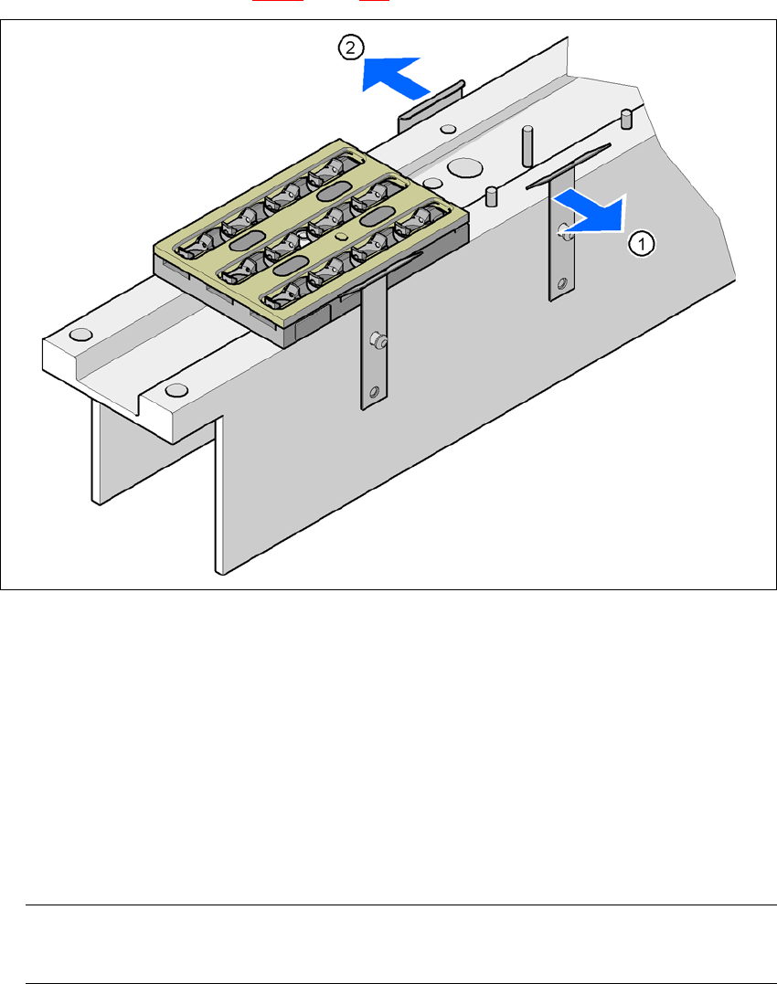
6.1.1.5 Assembly
Each nozzle changer (see Fig. 6.1 - 2, page 263) is fixed to the used tape channel.
6
Fig. 6.1 - 4 Assembly position
(1) Spring hook pointing toward the operator
(2) Retaining clamp pointing toward the PCB conveyor
→ Align the nozzle changer so that the moving spring hooks always point toward the operator,
while the retaining clamps always point toward the PCB conveyor.
6.1.1.6 Notes on operation
→ When you fill a magazine with a certain nozzle type for the first time, attach an adhesive label
to identify the type.
PLEASE NOTE 6
Fill the magazines off the machine and always replace complete magazines. 6
→ Open the locking plate and place the nozzles in the nozzle holders.
→ Close the locking plate so that the nozzles cannot drop out of the magazines.