00195741-0102_UM_D1_D2_SR605_EN.pdf - 第139页
User Manual SIPLACE D1/D2 3 Technical data for the machine From software version SR.605.xx 07/2008 EN Edition 3.9 Vision system 139 3.9.2 C&P component camera, type 29, 27 x 27, d igit al 3.9.2.1 Structure 3 Fig. 3.9…
3 Technical data for the machine User Manual SIPLACE D1/D2
3.9 Vision system From software version SR.605.xx 07/2008 EN Edition
138
3.9.1 C&P component camera, type 28, 18 x 18, digital
3.9.1.1 Structure
3
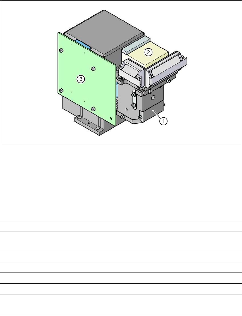
Fig. 3.9 - 2 C&P component camera, type 28, 18 x 18, digital
3
(1) Component camera lens and illumination
(2) Camera amplifier
(3) Illumination control
3.9.1.2 Technical data
3
Component dimensions 0.5 x 0.5 mm² to 18.7 x 18.7 mm²
Range of components 0402 to PLCC44 incl. BGA, μBGA, flip-chip, TSOP, QFP,
SO to SO32, DRAM
Min. lead pitch 0.5 mm
Min. lead width 0.2 mm
Min. ball pitch 0.35 mm
Min. ball diameter 0.2 mm
Field of vision 24.5 x 24.5 mm²
Method of illumination Front-illumination (5 levels, programmable as required)
User Manual SIPLACE D1/D2 3 Technical data for the machine
From software version SR.605.xx 07/2008 EN Edition 3.9 Vision system
139
3.9.2 C&P component camera, type 29, 27 x 27, digital
3.9.2.1 Structure
3
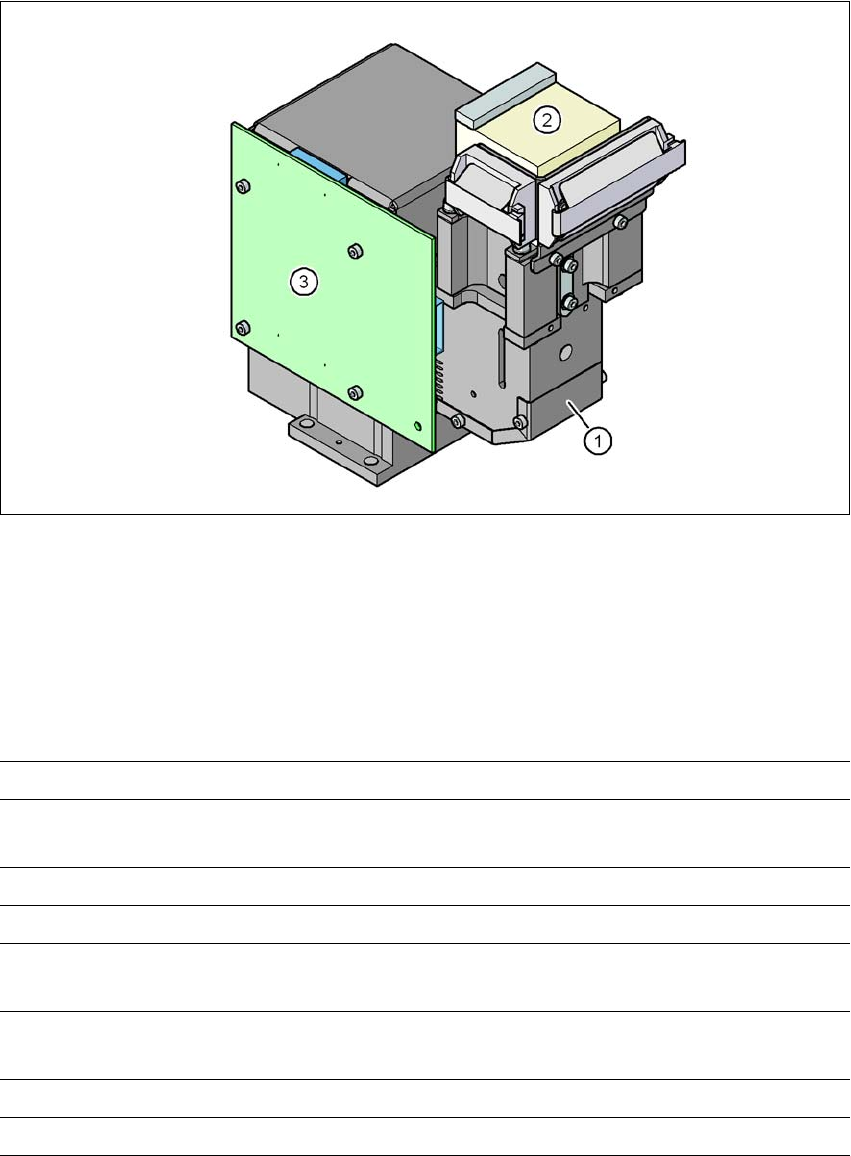
Fig. 3.9 - 3 C&P component camera, type 29, 27 x 27, digital
(1) Component camera lens and illumination
(2) Camera amplifier
(3) Illumination control
3.9.2.2 Technical data
3
Component dimensions 0.3 x 0.3 mm² to 18.7 x 18.7 mm²
Range of components 0201 to 27 x 27 mm²
PLCC, SO, QFP, TSDP, SOT, MELF, CHIP, IC BGA
Min. lead pitch 0.3 mm
Min. lead width 0.15 mm
Min. ball pitch 0.25 mm for components < 18 x 18 mm²
0.35 mm for components ≥18 x 18 mm²
Min. ball diameter 0.14 mm for components < 18 x 18 mm²
0.2 mm for components ≥ 18 x 18 mm²
Field of vision 32 x 32 mm²
Method of illumination Front-illumination (5 levels, programmable as required)
3 Technical data for the machine User Manual SIPLACE D1/D2
3.9 Vision system From software version SR.605.xx 07/2008 EN Edition
140
3.9.3 Stationary P&P component camera, type 36, 32 x 32, digital
3.9.3.1 Structure
3
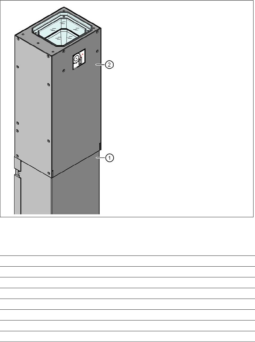
Fig. 3.9 - 4 Structure for the stationary P&P component camera, type 36, 32 x 32, digital
3.9.3.2 Technical data
3
(1) Camera housing with integral camera
and camera amplifier
(2) Glass plate - over the illumination and
lens levels
Component dimensions 0.8 x 0.8 mm² to 32 x 32 mm² (single measurement)
Range of components 0603, MELF, SO, PLCC, QFP, electrolytic capacitors, BGA
Min. lead pitch 0.4 mm
Min. lead width 0.24 mm
Min. ball pitch 0.56 mm
Min. ball diameter 0.32 mm
Field of vision 38 x 38 mm²
Method of illumination Front-illumination (6 levels, programmable as required)