00195741-0102_UM_D1_D2_SR605_EN.pdf - 第138页
3 Technical data for the machine User Manual SIPLACE D1/D2 3.9 Vision system From software ve rsion SR.605.xx 07/2008 EN Edition 138 3.9.1 C&P component camera, type 28, 18 x 18, digit al 3.9.1.1 Structure 3 Fig. 3.9…
User Manual SIPLACE D1/D2 3 Technical data for the machine
From software version SR.605.xx 07/2008 EN Edition 3.9 Vision system
137
3.9 Vision system
A component camera is integrated into each Collect&Place head (see Fig. 3.6 - 2 page 112 and
3.6 - 4
page 116).
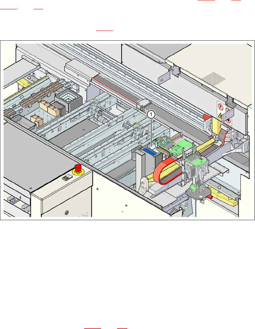
On the D1 machine, the stationary component camera, type 36, for the Pick&Place head is fixed
to the machine frame (item 1 in Fig. 3.9 - 1
).
3
Fig. 3.9 - 1 D1 machine: assembly positions for the stationary component camera, type 36
The component vision module is used to determine:
– the precise position of the components at the nozzle and
– the geometry of the package form.
The PCB vision module uses fiducials on the PCBs to determine:
– the position of the PCB,
– its rotation angle
– and the PCB skew.
The PCB camera (item 2 in Fig. 3.9 - 5
page 141 is fixed to the underside of the gantry. They use
fiducials on the feeder modules to determine the exact pick-up position of components, which is
particularly important for small components.
3 Technical data for the machine User Manual SIPLACE D1/D2
3.9 Vision system From software version SR.605.xx 07/2008 EN Edition
138
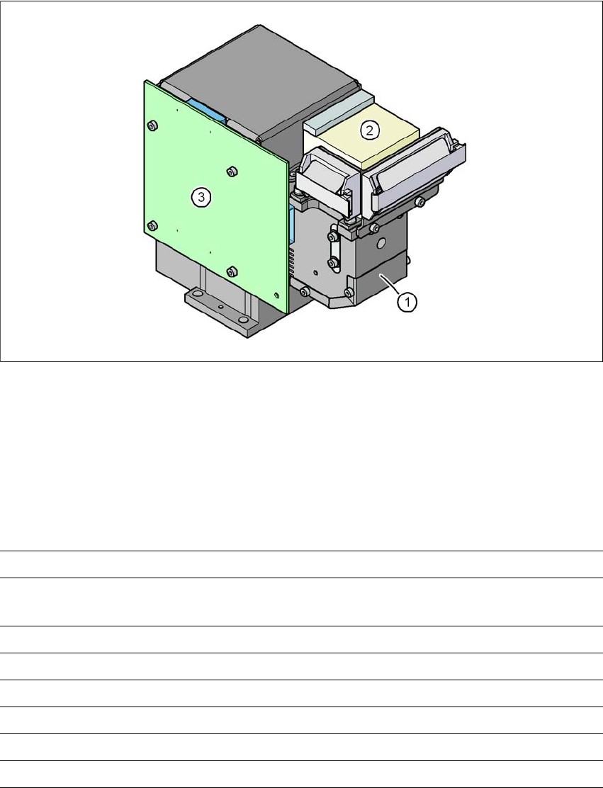
3.9.1 C&P component camera, type 28, 18 x 18, digital
3.9.1.1 Structure
3
Fig. 3.9 - 2 C&P component camera, type 28, 18 x 18, digital
3
(1) Component camera lens and illumination
(2) Camera amplifier
(3) Illumination control
3.9.1.2 Technical data
3
Component dimensions 0.5 x 0.5 mm² to 18.7 x 18.7 mm²
Range of components 0402 to PLCC44 incl. BGA, μBGA, flip-chip, TSOP, QFP,
SO to SO32, DRAM
Min. lead pitch 0.5 mm
Min. lead width 0.2 mm
Min. ball pitch 0.35 mm
Min. ball diameter 0.2 mm
Field of vision 24.5 x 24.5 mm²
Method of illumination Front-illumination (5 levels, programmable as required)
User Manual SIPLACE D1/D2 3 Technical data for the machine
From software version SR.605.xx 07/2008 EN Edition 3.9 Vision system
139
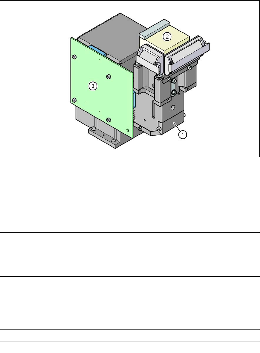
3.9.2 C&P component camera, type 29, 27 x 27, digital
3.9.2.1 Structure
3
Fig. 3.9 - 3 C&P component camera, type 29, 27 x 27, digital
(1) Component camera lens and illumination
(2) Camera amplifier
(3) Illumination control
3.9.2.2 Technical data
3
Component dimensions 0.3 x 0.3 mm² to 18.7 x 18.7 mm²
Range of components 0201 to 27 x 27 mm²
PLCC, SO, QFP, TSDP, SOT, MELF, CHIP, IC BGA
Min. lead pitch 0.3 mm
Min. lead width 0.15 mm
Min. ball pitch 0.25 mm for components < 18 x 18 mm²
0.35 mm for components ≥18 x 18 mm²
Min. ball diameter 0.14 mm for components < 18 x 18 mm²
0.2 mm for components ≥ 18 x 18 mm²
Field of vision 32 x 32 mm²
Method of illumination Front-illumination (5 levels, programmable as required)