00195741-0102_UM_D1_D2_SR605_EN.pdf - 第256页
5 Tasks for the operating personnel User Manual SIPLACE D1/D2 5.10 Docking the component trolley in or out From software version SR.605.xx 07/2008 EN Edition 256 → T urn the switch on the component t able (item 2 in Fig.…
User Manual SIPLACE D1/D2 5 Tasks for the operating personnel
From software version SR.605.xx 07/2008 EN Edition 5.10 Docking the component trolley in or out
255
5.10 Docking the component trolley in or out
5.10.1 Safety instructions for docking component trolleys in or out
WARNING 5
→ Please follow the safety instructions for docking the component trolleys in and out described
in Section 2.5.2, page 59.
5.10.2 Docking out the component trolley
→ Click on the STOP PROCESSING PCB icon in the MAIN VIEW menu.
The PCB in progress will be completed. The icons of the single functions menu will then be
activated. 5
→ Click on the desired icon SINGLE FUNCTIONS GANTRY.
→ Select GANTRY FUNCTIONS.
→ From this menu, click on the GO TO SET-UP POSITION button.
All the placement heads will move across the PCB conveyor to prevent them being damaged
when the component trolley is changed. 5
→ Open the protective cover of the selected gantry.
WARNING DANGER OF CRUSHING 5
When raising the component table, never reach into the gap between the feeders and the
used tape channel. 5
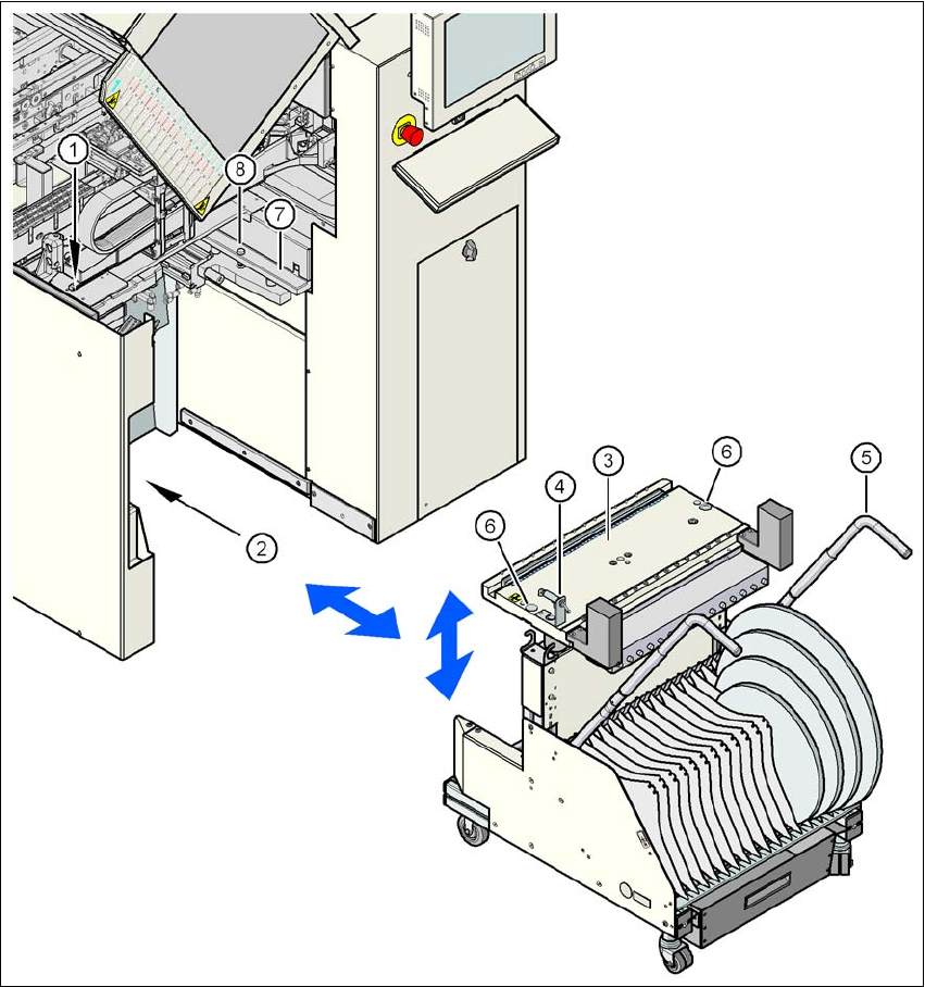
→ Turn the switch on the component table (item 4 in Fig. 5.10 - 2
, page 257) up.
→ Press the button on the machine frame (item 1 in Fig. 5.10 - 2
, page 257) until the component
table (item 8 in Fig. 5.10 - 2
, page 257) has reached the upper final position.
→ Unplug the supply cable of the component trolley from the socket on the station (item 2 in Fig.
5.10 - 2
, page 257).
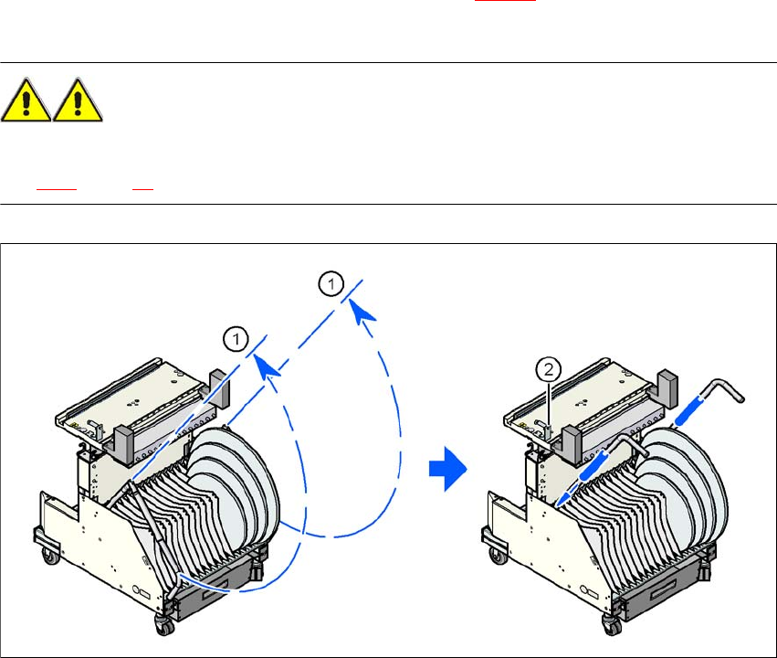
→ Swivel the two handles up (item 1 in Fig. 5.10 - 1
, page 256).
→ With both hands on the handles, pull the component trolley out of the machine.
5 Tasks for the operating personnel User Manual SIPLACE D1/D2
5.10 Docking the component trolley in or out From software version SR.605.xx 07/2008 EN Edition
256
→ Turn the switch on the component table (item 2 in Fig. 5.10 - 1) down. The component table
is lowered.
WARNING 5
→ Please follow the safety instructions for moving the component trolley described in Section
2.5.4, page 60.
5
Fig. 5.10 - 1 Component trolley - swivel handles up to push
5
(1) Handle
(2) Button for lowering the component table
Switch below: The component table is lowered
Switch up: The raised component table remains in this position.
User Manual SIPLACE D1/D2 5 Tasks for the operating personnel
From software version SR.605.xx 07/2008 EN Edition 5.10 Docking the component trolley in or out
257
Fig. 5.10 - 2 Docking the component trolley in or out
5
(1) Button for raising the component table
(2) Plug for connecting the component trolley cable
(3) Component table (can be raised or lowered)
(4) Button for lowering the component table
(5) component trolley handle
(6) Centering hole for the centering pins
(7) Supporting surface for the component table (right and left)
(8) Centering pin for the component table