00195741-0102_UM_D1_D2_SR605_EN.pdf - 第123页
User Manual SIPLACE D1/D2 3 Technical data for the machine From software version SR.605.xx 07/2008 EN Edition 3.7 Gantry system 123 3.7.2 Structure of the X axis 3 Fig. 3.7 - 2 S tructure of the X axis The X axis essenti…
3 Technical data for the machine User Manual SIPLACE D1/D2
3.7 Gantry system From software version SR.605.xx 07/2008 EN Edition
122
3.7 Gantry system
3.7.1 Position of the gantries
3
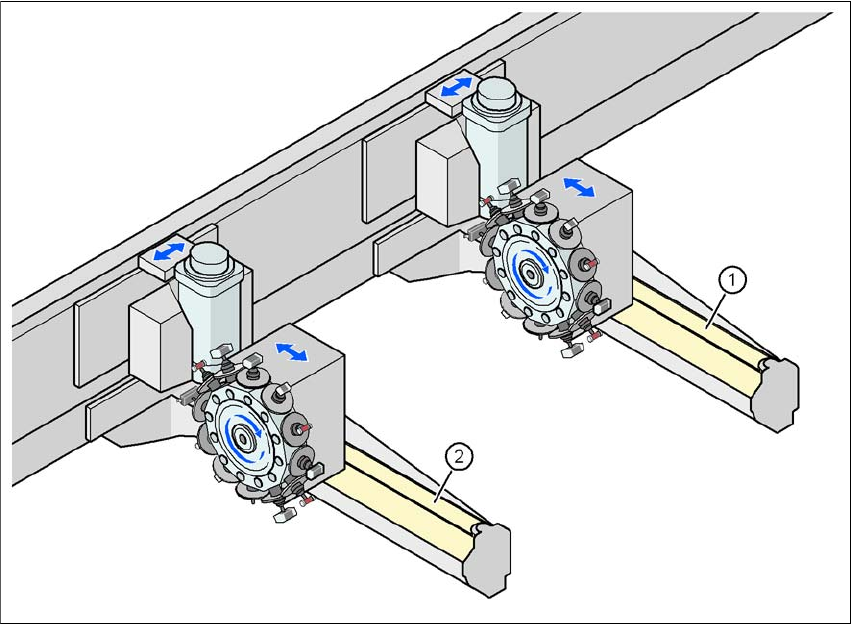
Fig. 3.7 - 1 Position of the gantries
(1) Gantry 1 (D1 and D2)
(2) Gantry 2 (D2)
The gantry system consists of two functional groups
–X axis and
–Y axis
User Manual SIPLACE D1/D2 3 Technical data for the machine
From software version SR.605.xx 07/2008 EN Edition 3.7 Gantry system
123
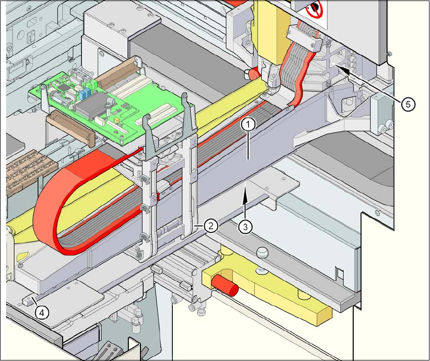
3.7.2 Structure of the X axis
3
Fig. 3.7 - 2 Structure of the X axis
The X axis essentially consists of the following main modules:
– Gantry arm (1)
– Head mount (2)
– Linear measuring system (3)
– X axis guide system (4)
– X axis three-phase AC servomotor (5)
The head mount holds the following components:
– Sub-gantry camera (camera for the PCB vision module)
– Head board
– Measuring head for the X axis measuring system
– Collect&Place head (SIPLACE D2)
– Collect&Place head and Pick&Place head (SIPLACE D1)
3 Technical data for the machine User Manual SIPLACE D1/D2
3.7 Gantry system From software version SR.605.xx 07/2008 EN Edition
124
3.7.3 Technical data for the X axis
3
3.7.4 Structure of the Y axis
3
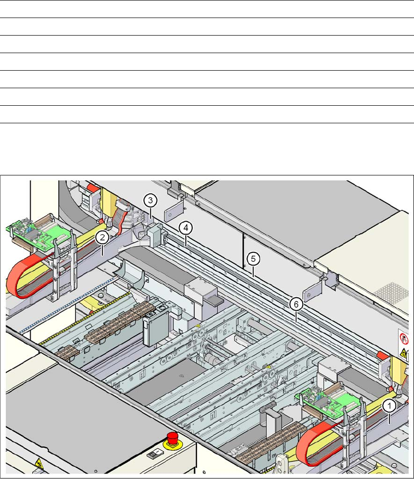
Fig. 3.7 - 3 Structure of the Y axis on the example of the D2 machine
Drive Three-phase AC servomotor/toothed belt
Maximum speed 2.5 m/s
Traversing path 470 mm
Distance measuring system Metal linear scale
Measuring length 520 mm
Scale length 520 mm
Resolution 1 μm
(1) Gantry 1 (SIPLACE D1/D2) (4) Guide system
(2) Gantry 2 (SIPLACE D2) (5) Permanent magnet
(3) Adapter plate (6) Measuring system