FUJI NXT Programming Manual QD004-18.pdf - 第101页
QD004-18 4. Part Data Settings NXT Programming Manual 91 Motor Gripping Force Specify the f orce used t o hold th e part dur ing pickup. Th is setting is only valid for the OF head. Tolerance X / Toleranc e Y This sets t…
4. Part Data Settings QD004-18
90 NXT Programming Manual
while if the setting is "No" the pressure control is not used when the part is picked. This
setting is only applicable for heads with this sensor. This setting has priority over soft pick-
up settings.
Do Prerotation
This setting is ignored by the NXT. Prerotation is automatically performed on heads that
support this function.
Do Prerotation for Custom Nozzle
Specify whether or not to rotate parts to (or near to) the placement angle prior to vision
processing when using custom nozzles. This setting is only valid for the H01, H02, and G04
heads.
Do Part Height Check
Specify whether or not to perform a height check of the part. This setting is only used if the
head can check the part height (for example, H12SQ).
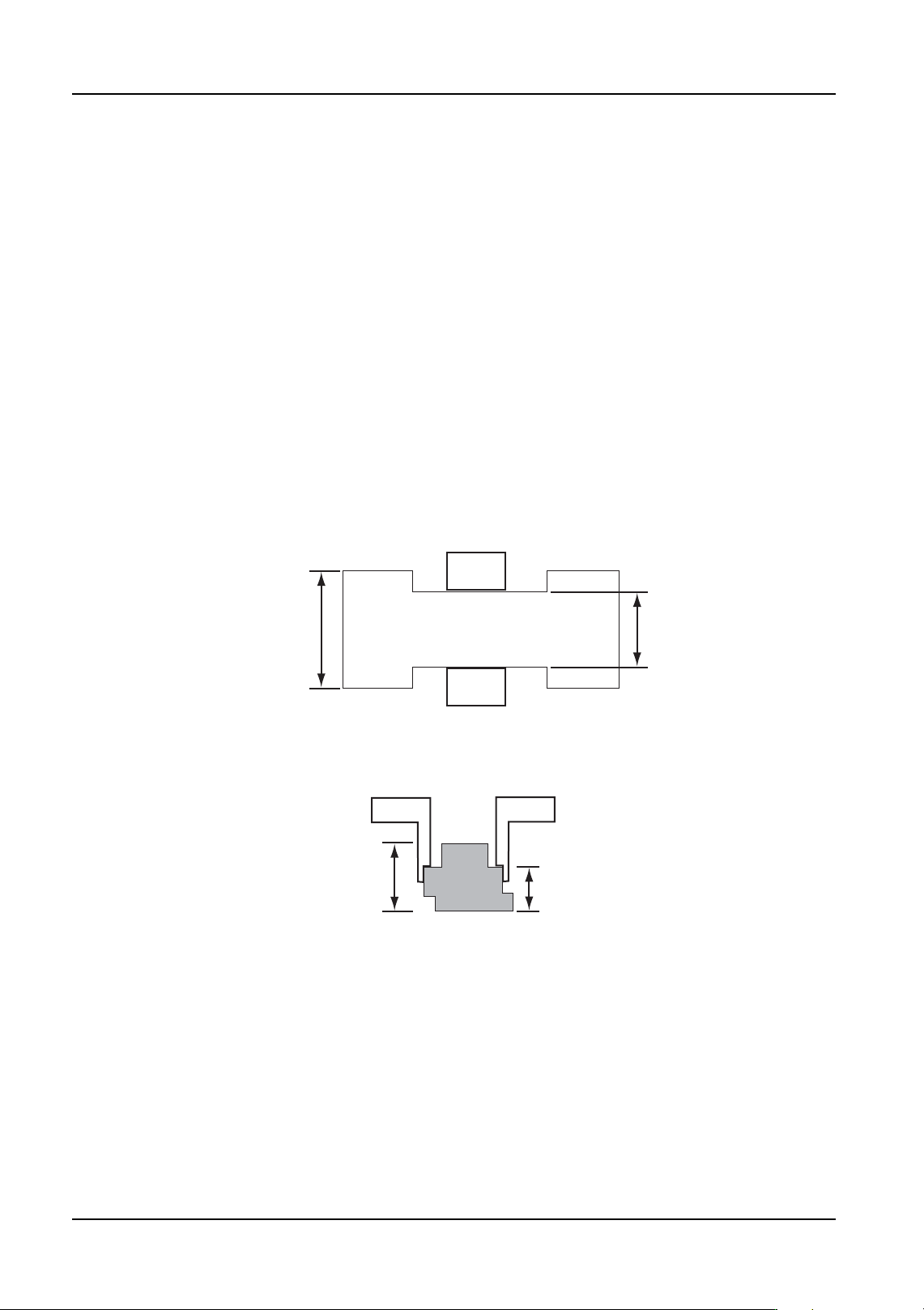
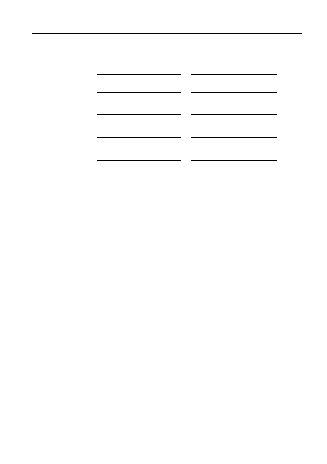
Clamp Width
Specify the width of the part at the clamping position. This setting is only valid for the OF
head.
Actual Pickup Body Height
Specify the height of the part at the clamping position.
Clamp Margin
Specify the gap between the claw width during clamping and the actual claw width. This
setting is only valid for the OF head.
Part Body
Claw
Width
01PRG063E
Claw
Clamp Width
Body Height
01PRG064E
Claw
Actual Pickup Body Height
Claw
Part Body
QD004-18 4. Part Data Settings
NXT Programming Manual 91
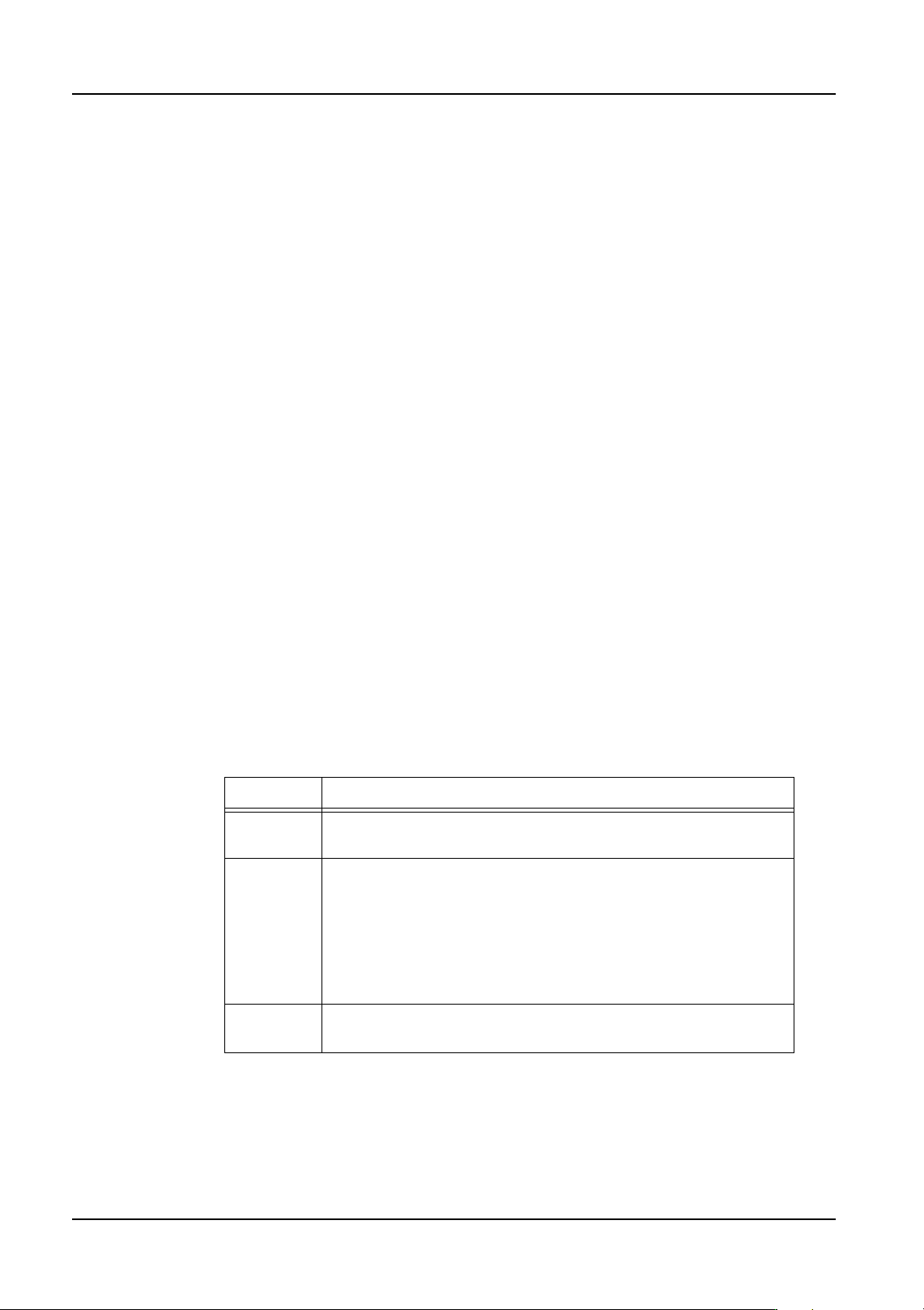
Motor Gripping Force
Specify the force used to hold the part during pickup. This setting is only valid for the OF
head.
Tolerance X / Tolerance Y
This sets the tolerance for misalignment of the nozzle center and part center. The machine
rejects the part if these tolerances are exceeded.
Tolerance Q
Specify the tolerance for misalignments between the nozzle and part centers in the Q
direction. Generally, 30 degrees is entered for Tolerance Q. For parts with a body
dimension larger than 20 mm, input 15 degrees.
Shuttle Speed
Specify the shuttle speed at which an MTU tray is loaded into the machine. A setting of 4
is the fastest speed for a TU-L and 5 is the fastest for a TU-LT, while a setting of 1 is the
slowest.
Magazine Speed
Specify the acceleration/deceleration rate used when raising and lowering trays in the MTU.
Process - Place
Do Place Check
Specifies whether or not a check to see if the part is still on the nozzle after placement is
performed. This setting is only used for heads that support this function (for example, H01,
H02, G04, H12SQ).
Offset X
Specify an offset value for part placement in the X-direction.
Offset Y
Specify an offset value for part placement in the Y-direction.
Offset Z
Specify an offset value for part placement height.
Pressure
Specify the force to be used to place a part using this shape when placed using a
Setting Part holding force
(N)
Setting Part holding force
(N)
0 6.7 6 9.7
17.2 710.2
27.7 810.7
38.2 911.2
4 8.7 10 11.7
59.2 - -
4. Part Data Settings QD004-18
92 NXT Programming Manual
compatible head. The valid range for the NXT is 220 gf to 1020 gf. If "0" is specified here,
the part is placed using no pressure control. When settings less than the minimum are
specified, the part is placed using the minimum pressure. When settings more than
maximum are specified, the part is placed using the maximum pressure. This setting is only
applicable for heads that support this function. This setting has priority over soft placement
settings.
Transport Speed
Specify, as a percentage of the maximum transport speed, the speed at which the placing
head carries the part from the pick-up position to the placing position.
Transport Speed Z
Specify the maximum speed at which the nozzle moves along the Z axis while transporting
a part (i.e., from pickup to placement).
Transport Speed Q
Specify the maximum speed at which the nozzle rotates while transporting a part (I.e., from
pickup to placement).
Soft Place Speed
This sets the Z-axis transport speed. This is the speed at which the part is lowered to the
surface of the board. If this speed is too high, the part will spring back when the nozzle
retracts, resulting in a misalignment.
Place Motion Selection (from NXT V3.10)
Specify the pressure (torque) method to be used for insertation pressure. In order to use
this function, Fuji Flexa V2.2.0 or higher must be used. The default setting of "0" disables
this function. Enter a value between 1 to 4 to enable insertion pressure placing. If 5 is
entered, insertion pressure is not used but if a claw is used to pick the part, the margin
between the top of the part and the ledge on the claw will be 0 mm (normally there is a
clearance of 0.5 mm).
Note: Always ensure to use backup pins underneath the panel when using insertion pressure.
Note: When an insertion error occurs and the user then clears the error, the machine determines
that the part has been placed and proceeds to the next placement sequence when
production is resumed. (Recovery is not performed)
Placing Thrust Pressure
Specify the force between 39.2 N to 98 N to be used to insert the part in newtons when
Setting Description
0 Insertion pressure is not used and the part is picked up and
placed normally.
1 to 4 Any setting in this range is treated the same. Insertion pressure
is used for placement. The part is picked up normally and during
placement, the torque amount specified in [Placing Thrust
Pressure] is used. If the torque is not reached in the proper
placing height range, an error occurs and the part is not placed.
(Operation is different for these settings for older machines. In
order to preserve compatibility with older machines, this is used
no matter what setting is specified.)
5 Insertion pressure is not used and the part is picked up and
placed normally.