FUJI NXT Programming Manual QD004-18.pdf - 第126页
4. Part Data Settings QD004-18 116 NXT Programming Manual • Leads on only o ne side • Leads on two opposite sides • Leads on two adjacent sides • Leads on three sides • Leads on four sides The center moves depending on t…
QD004-18 4. Part Data Settings
NXT Programming Manual 115
4.6 Vision Type Details
4.6.1 Part reference point
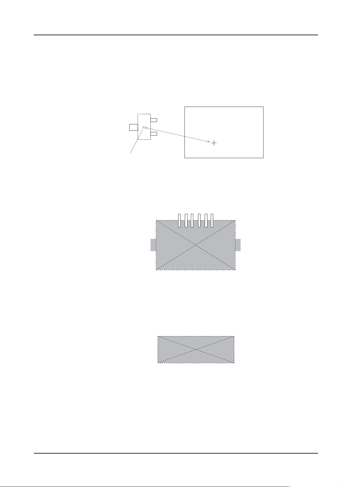
The part reference point is defined as the point on the part that is aligned with the placing
coordinates on the panel when the part is placed.
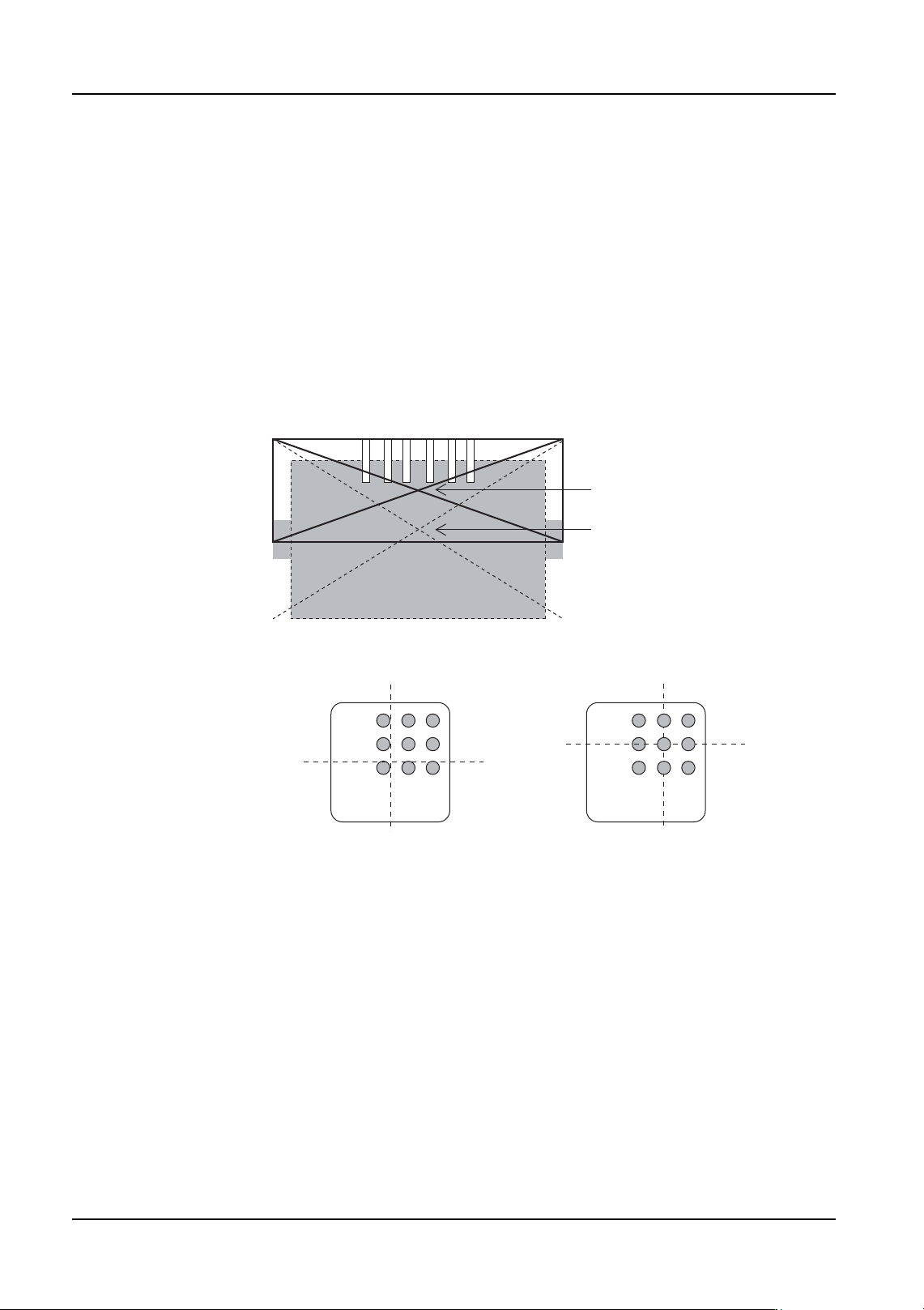
Body center
The center is taken from the outer-most points of the body; top, bottom, left, and right.
(The leads have no affect on the placing coordinates.)
Part center
The part center is defined as follows.
1. Part center of non-leaded parts
The part center is taken from the outer-most points; top, bottom, left, and right.
2. Part center of parts with leads (ball grids)
The part center is calculated from the coordinates of the lead ends or from the center
coordinates of the ball grid taken from the outer-most points; top, bottom, left, and right.
The point of intersection of the center line from the outer-most points top to bottom and
the center line from the outer-most points left to right yields the part center. However, if
there are leads or a ball grid on only one side, a theoretical part center is defined based
on the part data.
The following combinations are possible based on the lead positions.
Part
Placing coordinates (X, Y)
Panel
Reference point
Match
4. Part Data Settings QD004-18
116 NXT Programming Manual
• Leads on only one side
• Leads on two opposite sides
• Leads on two adjacent sides
• Leads on three sides
• Leads on four sides
The center moves depending on the lead positions, lead lengths, and lead widths.
For parts with leads on three sides, the part center is defined as the point of intersection of
the center line from the outer-most points top to bottom and the center line from the outer-
most points left to right. As a result, the part center required for placement differs from the
actual placing position.
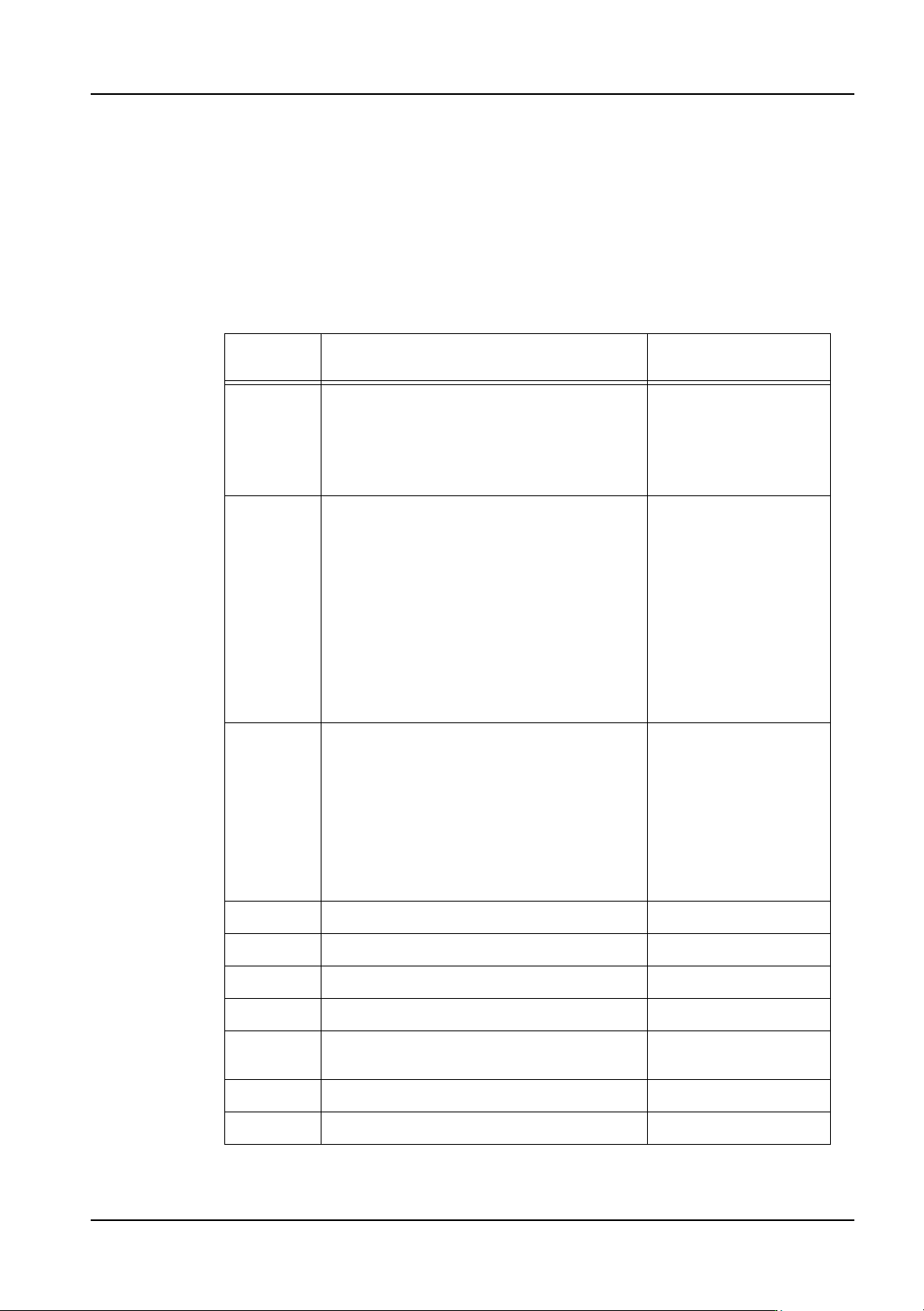
Ball grid body center and part center
Calculated part center
Theoretical part cente
r
Part reference point: body center
Part reference point: part center
QD004-18 4. Part Data Settings
NXT Programming Manual 117
4.6.2 NXT vision types
This section provides a list of the vision types for the NXT and an explanation of the
processing method used for each type. It is possible to use older vision types for other Fuji
machines in some cases. When making part data, if the parts are to be shared between
the NXT and other Fuji machines, use the old vision types in the “generic” section and enter
overrides for the NXT vision type when necessary. Refer to 4.7 "Compatibility with Existing
Part Data" for details.
Select the appropriate vision type from the following list of algorithms.
Vision
Type
Part Types Note
18 MPA (uses VPDplus) Supported V3.55 and
later.
19 MPA (uses VPDplus) With lead checks,
supported V3.90 and
later.
60 Rectangular chips
61 Tantalum spragues
62 Resistor networks, MELFs
63 Tantalum spragues Polarity check
performed
65 Aluminum electrolytic capacitors
66 Rectangular chips (skewed pickup check
function)
70 (75) Power transistors
71 Trimmer resisters, trimmer capacitors
72 HEMT Supplied at 0 degrees
73 HEMT Supplied at 45 degrees
74 Trimmer resisters, trimmer capacitors Polarity check
performed
80 Round shaped parts (no polarity)
123 (128) IC-type leaded parts Supports multiframe
124 (129) J-leaded parts
140 (145) Flip-chips
142 (147) Black bodied parts with irregular bump
patterns
Supports multiframe
143 (148) CCGA parts Supports multiframe
144 (149) LGA parts Supports multiframe