FUJI NXT Programming Manual QD004-18.pdf - 第135页
QD004-18 4. Part Data Settings NXT Programming Manual 125 Vision Type 123 (128) IC- type leaded parts Vision Type 124 (129) J-leade d parts Enter the body size and element infor mation in part data. Due to the use of fro…
4. Part Data Settings QD004-18
124 NXT Programming Manual
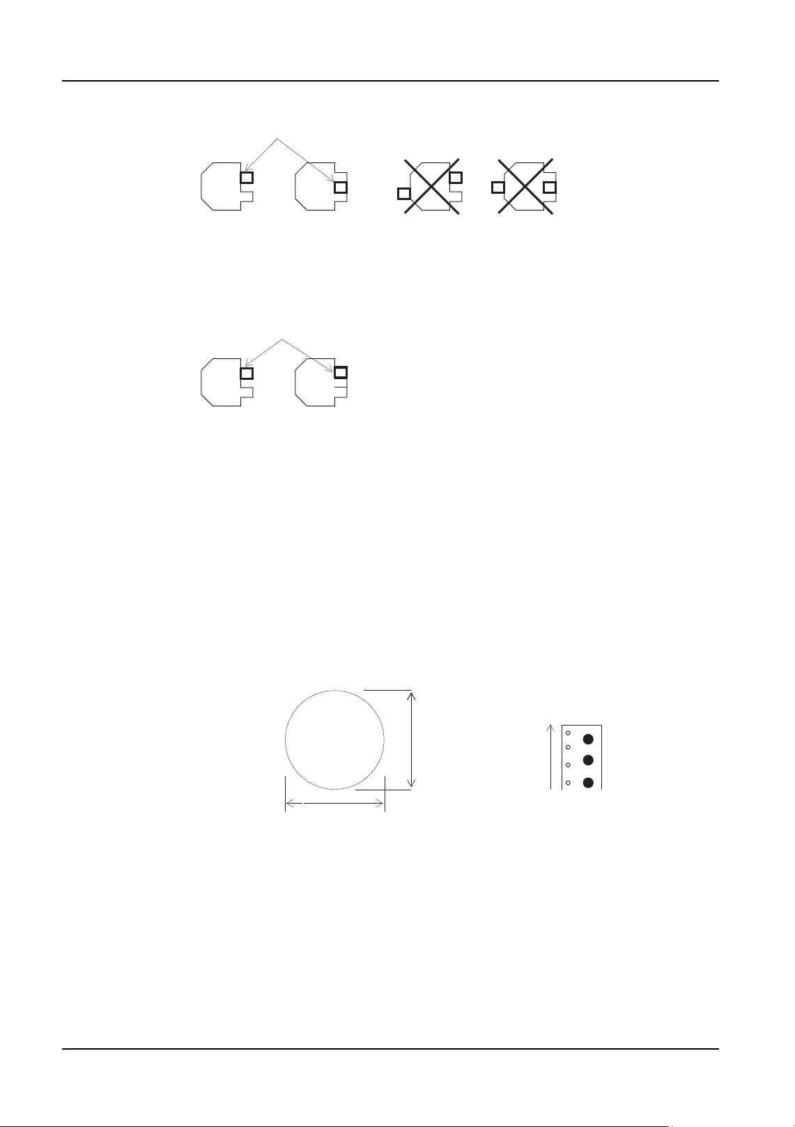
Vision Type 80 Round shaped parts
Enter only the body size in part data. There is no need to enter element information. The
reference point for the part is the part center.
2-pin 3-pin
Fig. 1 Detected lead position when performing direction inspection
Detected lead
Direction inspection is impossible if
a protrusion of the same shape as the lead exists
diagonally across from a lead.
Fig 2. Set as 2-pin part in part data
Detected lead
2-pin 3-pin (no error occurs)
Direction 0 deg
Supply direction
Body size Y
Body size X
Round shaped part
QD004-18 4. Part Data Settings
NXT Programming Manual 125
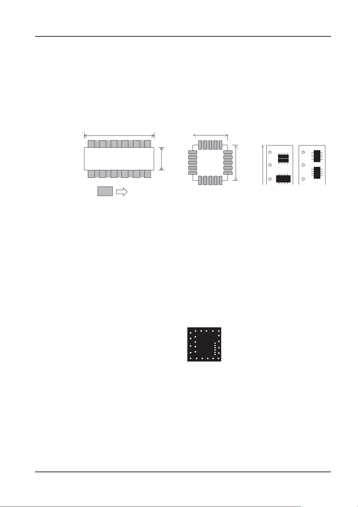
Vision Type 123 (128) IC- type leaded parts
Vision Type 124 (129) J-leaded parts
Enter the body size and element information in part data. Due to the use of frontlighting,
there are cases in which the acquired image may vary depending on the shape of the leads
and the lighting conditions. In such cases, it may be necessary to make adjustments to the
position, length and width of the lead information in element information. Vision types 123,
124 use the body center while vision types 128, 129 use the part center.
Vision Type 140 (145) Flip-chips
Enter the body size and element information in part data. Vision type 140 uses the body
center while vision type 145 uses the part center.
Due to the use of frontlighting, there are cases in which the image of the ball grid may vary
depending on the shape of the leads and the lighting conditions. In such cases, it may be
necessary to make adjustments to the ball grid position, length and width of the lead
information in element information.
Inspection of certain parts may not be possible due to variations in the body color and the
and the image of the ball grid.
SOIC
Direction 0 deg 90 deg
Element
Body
size
Y
Body size X
Supply direction
PLCC
Body size X
Body
size
Y
Flip chip
4. Part Data Settings QD004-18
126 NXT Programming Manual
Vision Type 142 (147) Black bodied parts with irregular bump patterns
Select this vision type for bump leaded parts with irregular bump patterns. Enter the body
size and element information in part data. Vision type 142 uses the body center while vision
type 147 uses the part center.
The following conditions apply to bump leads:
• There must be two or more bumps on the part.
• The pitch must be equal or greater to two times the bump diameter. However,
for parts with only two bumps, the pitch must be greater or equal to one sixth (1/
6) of the average body size in all directions.
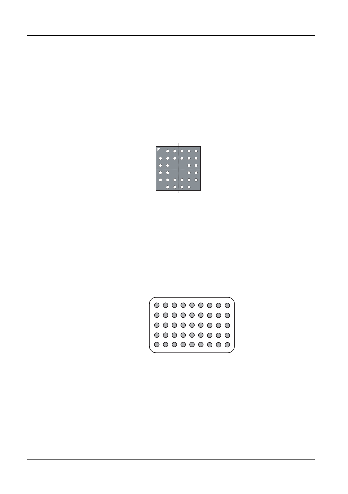
Vision Type 143 (148) Ceramic column grid array (CCGA) parts
Enter the body size and element information in part data. Vision type 143 uses the body
center while vision type 148 uses the part center.
Due to the use of frontlighting, there are cases in which the image of the ball grid may vary
depending on the shape of the leads and the lighting conditions. In such cases, it may be
necessary to make adjustments to the ball grid position, length and width of the lead
information in element information.
Vision Type 144 (149) Land grid array (LGA) parts
Enter the body size and element information in part data. Vision type 144 uses the body
center while vision type 149 uses the part center.
Vision Type 151 (156) Black connectors placed using a mechanical chuck
Enter the body size and element information in part data. It is necessary to create separate
element information for leads of different width and length. Vision type 151 uses the body
center while vision type 156 uses the part center.
NXTPRG047
CCGA