FUJI NXT Programming Manual QD004-18.pdf - 第29页
QD004-18 3. Job Builder NXT Programming Manual 19 Specifying the modules for an NXT After adding the NXT line, it is very im portant to confi gure the mo dules to match the modules in the cu rrent machine. Since item s a…
3. Job Builder QD004-18
18 NXT Programming Manual
Nozzle station
nozzle allocation
method
Specify the nozzle station nozzle arrangement method.
"Minimum" arranges for the minimum number nozzles
required by the head. "Maximum" arranges for the
maximum number of nozzles allowable in the station.
Setting Description
QD004-18 3. Job Builder
NXT Programming Manual 19
Specifying the modules for an NXT
After adding the NXT line, it is very important to configure the modules to match the
modules in the current machine. Since items and modules are easily interchanged, always
be sure to check the current module configuration.
1. There are several tabs at the bottom of the [Machine Configuration] pane. The second
tab is [Modules] and this is the location where the modules are set. Click this tab.
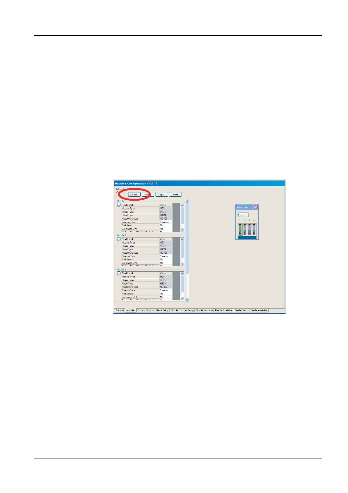
2. Click [Select] from the [Module Edit] group. A small dialog box displays with a
representation of the current NXT module configuration.
• Click a module in this dialog box to display that module in the information area.
• By using this dialog box, it is easy to navigate and understand the current
module configuration. In addition, this dialog box can be used to jump to
different modules on other tabs such as [Nozzle Changer Setup], and [Feeder
Setup].
3. Check the current modules. If the number and type of modules is correct in the module
information area then proceed to 13.
4. If the number of modules is incorrect, click [Add] and in the dialog box that displays,
specify the position for the new module. Once the desired position has been specified,
click [OK] and the module is added to the specified position using the default module
settings. Continue adding modules until the number of modules is correct for the NXT
machine.
Note: The NXT “machine” in Fuji Flexa is comprised of multiple bases that are next to each other.
One NXT machine can be created with up to 32 modules in this manner (e.g., eight 4M
bases with 4 M3 modules on each base). In this module configuration, the NXT machine
will have the number of modules that all of the bases put together have regardless of the
fact that the bases are different. For details on making the line configuration settings for the
NXT, refer to the “Setting Up a Line with a NXT” chapter in the NXT Setup Manual.
Note: Do not use [Copy] to add a new module. Copy only will replace the settings of an existing
module with the settings from the copied module. This is a convenient feature to use after
adding new modules to apply the same settings to the new modules.
01PRG-0054E
3. Job Builder QD004-18
20 NXT Programming Manual
5. Once all of the necessary modules are present, check the module configuration.
6. If the configuration needs to be changed, click the [...] button to the left of the module
information area. A dialog box displays with the possible module type and stage type
configurations.
Note: It is possible to change the individual values for the different fields. However, if a invalid
setting is selected, the text for the settings turns red to indicate that the selected values are
incorrect.
7. Click the button that has the correct module type for the selected module. The selected
settings are applied to the selected module and the possible choices for the selected
stage then are displayed. There are no more options if a conveyor unit is selected so
the dialog box is closed.
8. Click the button that has the correct stage configuration (feeder/tray setup) for the
selected module. The selected settings are applied to the selected module and the
possible choices for the selected option then are displayed.
9. Click the button that has the correct head type for the selected module. The selected
settings are applied to the selected module and the possible choices for the selected
option then are displayed. There are no more options if a glue head is selected so the
dialog box is closed.
10.Click the button that has the correct nozzle station for the selected module. The
selected settings are applied to the selected module and the dialog box is closed.
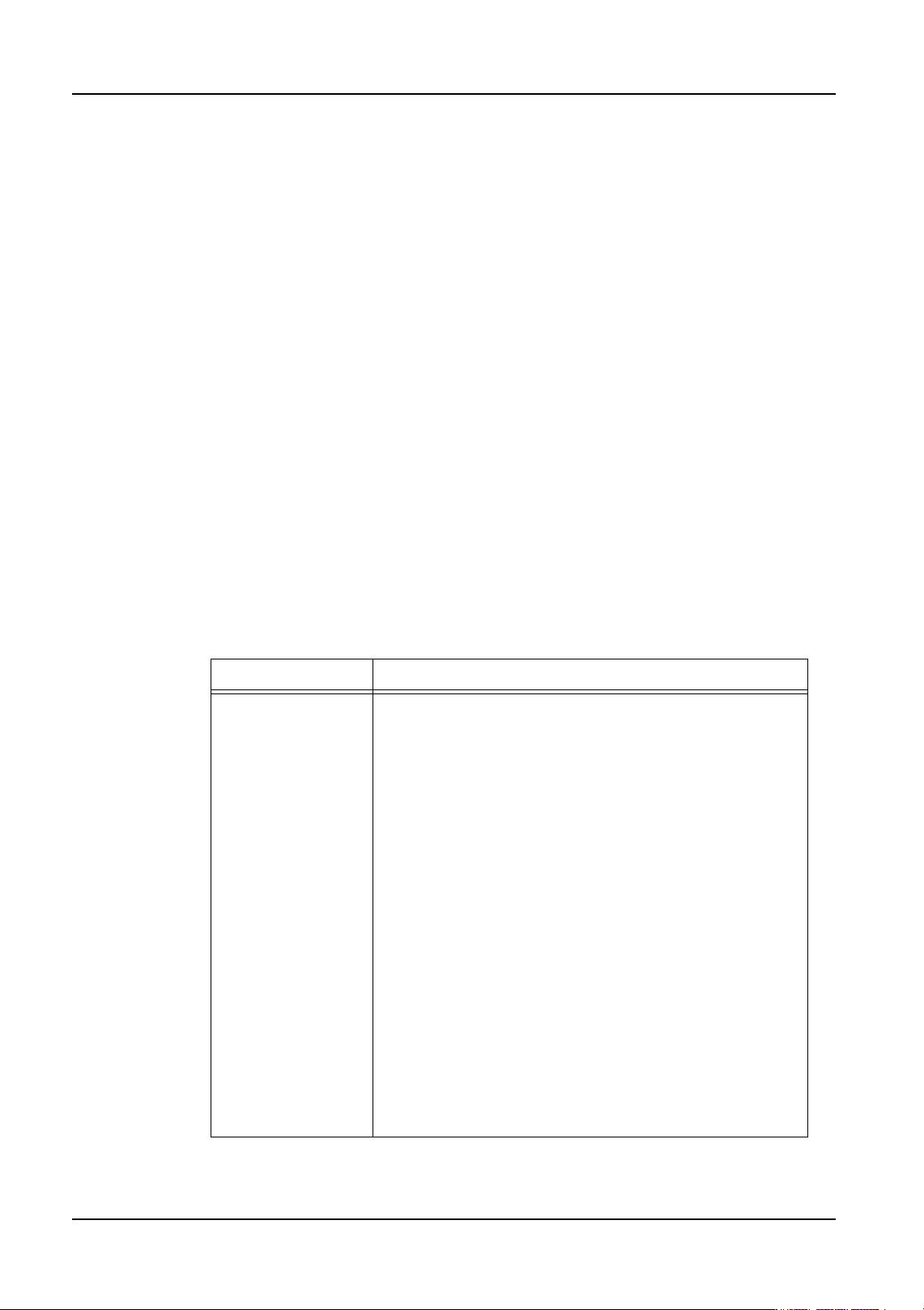
11.Specify any of the other settings that have a white background for the value cells as
necessary. Refer to the table below for information.
Setting Description
Camera Type Sets the parts camera type.
Standard[P04]: (heads: all (standard except for OF))
This is a standard frontlight camera. This camera is for
general use.
Sidelight: (heads: H01, H02, OF (Standard))
This is a sidelight camera. Use this camera when vision
processing using sidelight is required, such as for parts
with leads.
P03: (heads: H01, H02, G04, F04)
The resolution of this camera is higher than standard
camera. Use this camera when other cameras cannot
vision process very small bumps, such as those on CSPs
and flip chips, or very small fiducial marks.
High Resolution[P014]: (heads: H01, H02, G04, F04)
This is a high-resolution camera. Use this camera when
other cameras cannot vision process very small bumps,
such as those on CSPs and flip chips, or very small fiducial
marks.
Wide View: (head: F04)
This is a wide-view camera. Use this camera when the
field of vision of the standard camera is too narrow. An
example is when 4 parts, such as memory elements
(TSOP), are simultaneously picked up by an F04 head.