FUJI NXT Programming Manual QD004-18.pdf - 第31页
QD004-18 3. Job Builder NXT Programming Manual 21 12.Repeat the previous steps, while selecting th e next module in the machine until all of the modules in the machin e have the correct con figuration. 13.If any pairs of…
3. Job Builder QD004-18
20 NXT Programming Manual
5. Once all of the necessary modules are present, check the module configuration.
6. If the configuration needs to be changed, click the [...] button to the left of the module
information area. A dialog box displays with the possible module type and stage type
configurations.
Note: It is possible to change the individual values for the different fields. However, if a invalid
setting is selected, the text for the settings turns red to indicate that the selected values are
incorrect.
7. Click the button that has the correct module type for the selected module. The selected
settings are applied to the selected module and the possible choices for the selected
stage then are displayed. There are no more options if a conveyor unit is selected so
the dialog box is closed.
8. Click the button that has the correct stage configuration (feeder/tray setup) for the
selected module. The selected settings are applied to the selected module and the
possible choices for the selected option then are displayed.
9. Click the button that has the correct head type for the selected module. The selected
settings are applied to the selected module and the possible choices for the selected
option then are displayed. There are no more options if a glue head is selected so the
dialog box is closed.
10.Click the button that has the correct nozzle station for the selected module. The
selected settings are applied to the selected module and the dialog box is closed.
11.Specify any of the other settings that have a white background for the value cells as
necessary. Refer to the table below for information.
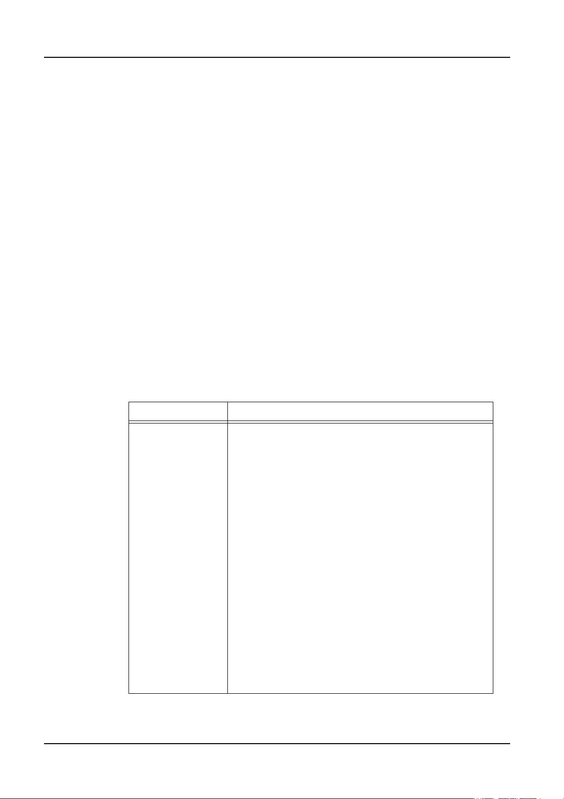
Setting Description
Camera Type Sets the parts camera type.
Standard[P04]: (heads: all (standard except for OF))
This is a standard frontlight camera. This camera is for
general use.
Sidelight: (heads: H01, H02, OF (Standard))
This is a sidelight camera. Use this camera when vision
processing using sidelight is required, such as for parts
with leads.
P03: (heads: H01, H02, G04, F04)
The resolution of this camera is higher than standard
camera. Use this camera when other cameras cannot
vision process very small bumps, such as those on CSPs
and flip chips, or very small fiducial marks.
High Resolution[P014]: (heads: H01, H02, G04, F04)
This is a high-resolution camera. Use this camera when
other cameras cannot vision process very small bumps,
such as those on CSPs and flip chips, or very small fiducial
marks.
Wide View: (head: F04)
This is a wide-view camera. Use this camera when the
field of vision of the standard camera is too narrow. An
example is when 4 parts, such as memory elements
(TSOP), are simultaneously picked up by an F04 head.
QD004-18 3. Job Builder
NXT Programming Manual 21
12.Repeat the previous steps, while selecting the next module in the machine until all of the
modules in the machine have the correct configuration.
13.If any pairs of M3 modules are to perform paired production, display the modules and
change the setting [Perform Paired Module Production] to “Yes” for both modules.
Specify any required stopping position offset. Repeat until all M3 modules that are to
perform paired module production have the correct setting.
Note: Paired module production is when two M3 modules clamp a single panel across the
conveyors for the modules and place parts on the same panel. Paired production can only
be performed between set pairs of M3 modules.
14.If the created module configuration is the standard setup for the selected NXT machine,
right-click the grey area outside of the setting area in the [Modules] tab and select [Save
as the Default Machine Configuration] to save the current module configuration as the
standard configuration. When the same machine is brought into a job from this point,
the module configuration will be the same as that just specified.
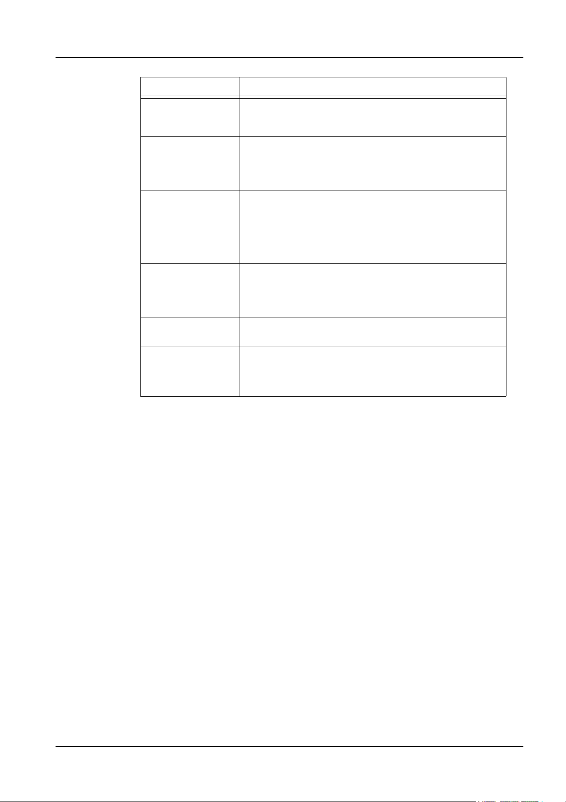
Camera Position This setting only displays when for M6 modules and is
used to specify the position of the camera. Only if a M6 has
a feeder pallet is this setting valid.
Part Sensor Specify whether a part presence check sensor is installed.
No: There is no parts sensor
Yes: A parts sensor is present
Part Sensor Type Specify the type of sensor to check for the presence of
parts.
-Sensor: A sensor is used to check.
-IPS: IPS is used to check for the presence of parts as
well as the part height.
Calibration Unit Specify whether a unit to check the nozzle load is installed.
No: There is no calibration unit
Yes: A calibration unit is present
Coplanarity This specifies whether or not the module is equipped with
coplanarity measuring unit. This is a NXT option.
Actual Cycle Time
Difference
Make a setting here when a difference between the
projected cycle time and actual production cycle time
exists for the module. Specify the difference between
these two cycle times.
Setting Description
3. Job Builder QD004-18
22 NXT Programming Manual
Specifying NXT machine processing options
Data about the processing of the job for the NXT machine must be entered. When a
machine with a certain name is added for the first time, the default process options are
used. This data must be checked and edited if it is not the correct processing options for
that machine.
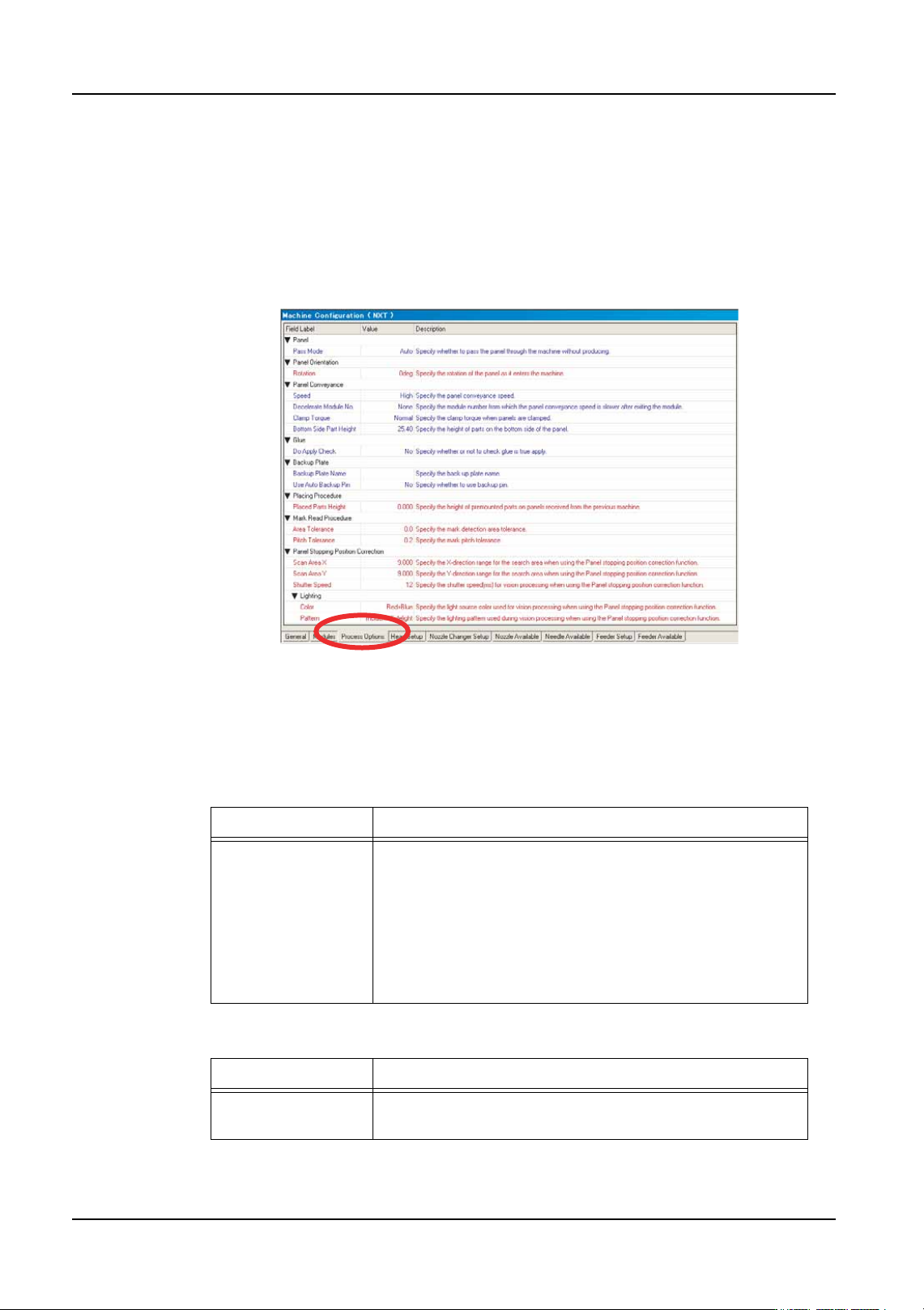
1. There are several tabs at the bottom of the [Machine Configuration] pane. Select the
[Process Options] tab to display the available process options for the machine
2. Enter the appropriate process settings for the machine. There are multiple groupings of
data. Refer to the tables below for information on the settings. More information on
special settings that relate to options can be found in the appropriate “Job Settings for
Advanced Functions” section.
Panel
Panel Orientation
Setting Description
Pass Mode Specify whether the machine should operate in pass
mode. When operating in pass mode the machine does
not produce any boards, and acts instead as a conveyor.
On: Operate using pass mode
Off: Normal production is performed.
Auto: The pass mode decision is made automatically
based on part allocation.
Setting Description
Rotation Specify the orientation of the panel as it enters the
machine.
01PRG-0055Ea