FUJI NXT Programming Manual QD004-18.pdf - 第138页
4. Part Data Settings QD004-18 128 NXT Programming Manual Vision Type 153 (158) Wh ite bodied connectors Enter the body size and element information in part da ta. It is necessary to create separate element informa tion …
QD004-18 4. Part Data Settings
NXT Programming Manual 127
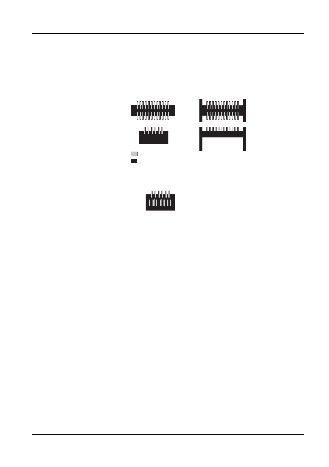
Vision Type 152 (157) Black bodied connectors
Enter the body size and element information in part data. It is necessary to create separate
element information for leads of different width and length. Vision type 152 uses the body
center while vision type 157 uses the part center.
<Examples of parts that can be inspected>
Lead
Black portion of the part (e.g. body or coating)
<Examples of parts that cannot be inspected>
The parts cannot be correctly inspected if any metal that
reflects light similarly to leads exists within the body
of the part.
4. Part Data Settings QD004-18
128 NXT Programming Manual
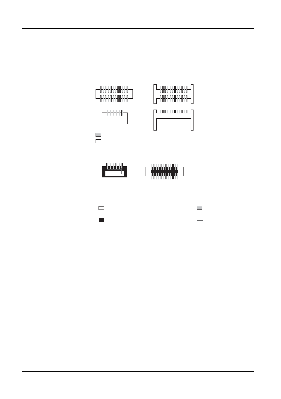
Vision Type 153 (158) White bodied connectors
Enter the body size and element information in part data. It is necessary to create separate
element information for leads of different width and length. Vision type 153 uses the body
center while vision type 158 uses the part center.
Vision Type 160 (165) White connector body detection
Enter the body size and element information for leads or projections. Vision type 160 uses
the body center while vision type 165 uses the part center. Element inspection is not
performed if the [Result] option for that element is set to "Don’t inspect".
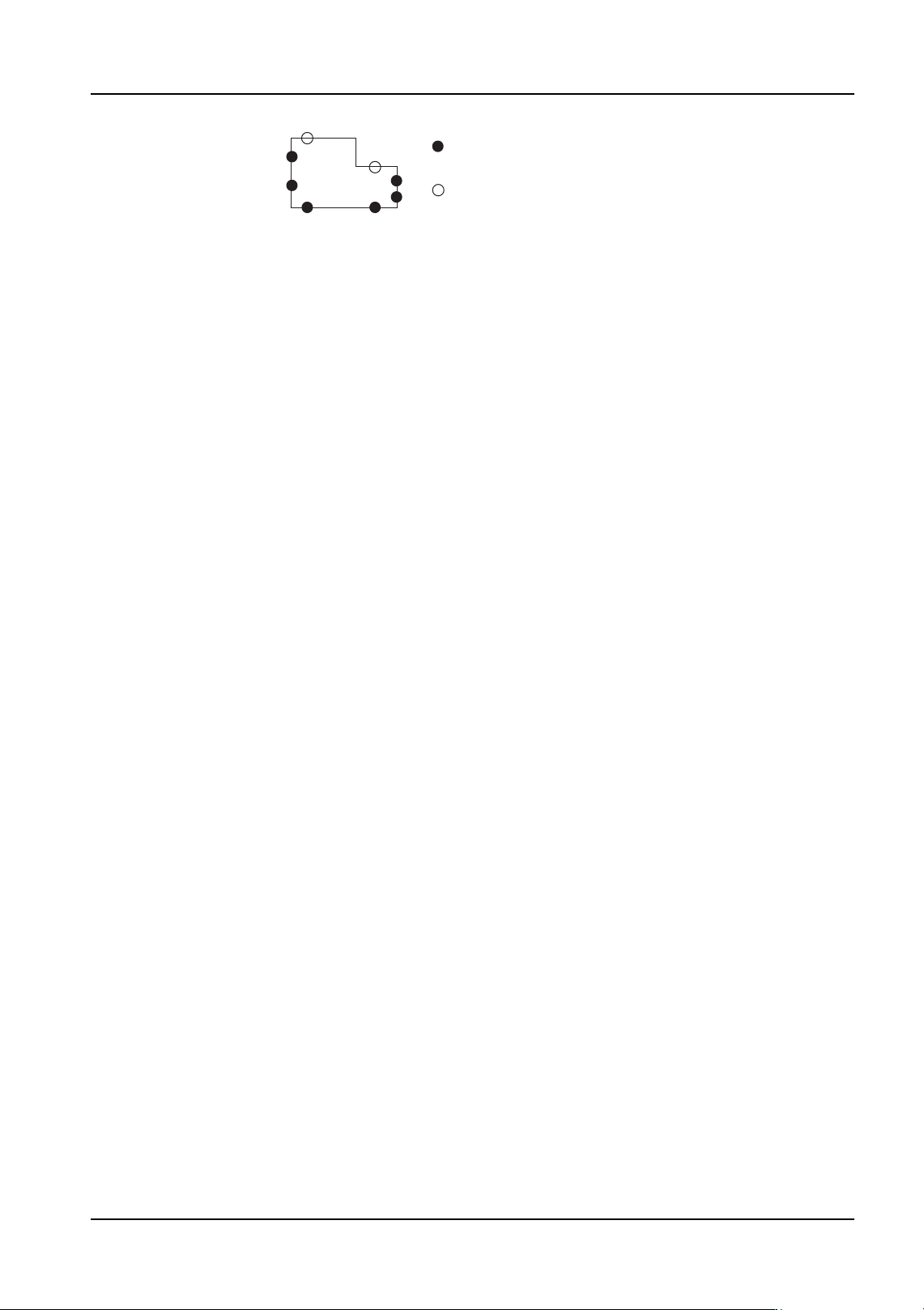
The body inspection points are automatically determined based on the data for leads and
projections specified in the element information. When detection positions cannot be
properly determined automatically, up to two elements per side can be specified in the
element information for the body inspection points. To specify body detection points,
specify the side and then enter the coordinates for the points to be inspected in [X] and [Y]
items for the position group and enter "0" for all other items for each “detection” element in
the element information.
Note: It is necessary to define leads in element information regardless of whether lead inspection
is to be performed for those leads or not.
Note: When the body detection option is specified, data should be specified such that there is a
minimum of one side where two points can be detected and a minimum of two sides where
one point can be detected. If there are an insufficient number of detection points, an error
occurs when data is registered.
Note: If the edges of the body of a part are not clearly projected, this may result in an error or a
drop in the placing accuracy.
Note: Correct processing cannot be performed if the nozzle protrudes over the edge of the part.
Note: If the straight line obtained from the specified detection points for the same line is not
parallel nor perpendicular to the straight line obtained from the detection points of another
side, then processing cannot be performed.
Lead
White portion of the part (e.g. body or coating)
<Examples of parts that can be inspected>
Lead
White portion of the part (e.g. body or coating)
The outer form of the part is used to determine the rough
positioning of the part. Therefore inspection of the part
is not possible if the outer form of the part cannot be determined.
Black portion of the part (e.g. body or coating)
Wiring
<Examples of parts that cannot be inspected>
QD004-18 4. Part Data Settings
NXT Programming Manual 129
Vision Type 170 Mechanical chuck part existence check
Use this vision type when part recognition is not possible using any other vision type. In the
shape data, set the vision type to 170, specify a setting for [Lead Brightness] and specify
the check area and select either 1 or 2 for the p_pattern in the element information. Based
on this data, if it is determined that the part has been picked, then the part is placed without
performing any correction based on vision. The part is positioned mechanically.
When vision processing is performed, the average greyscale of the area specified in the
element data is determined. This average is compared to the lead brightness setting and
based on the p_pattern setting it is determined whether or not the part is present.
If the p_pattern setting is 1 (dark) and the average greyscale value is higher than the lead
brightness setting, it is determined that the part is present. If the average grayscale is lower
than the lead brightness setting, then it is determined that the part is not present.
If the p_pattern setting is 2 (light) and the average greyscale value is lower than the lead
brightness setting, it is determined that the part is present. If the average grayscale is
higher than the lead brightness setting, then it is determined that the part is not present.
Note: Use a chuck with four claws when using this vision type.
: Points which can be used to define the part body.
: Points which cannot be used to define the part body.