FUJI NXT Programming Manual QD004-18.pdf - 第189页
QD004-18 6. Editing Jobs on the Machine (MEdit) NXT Programming Manual 179 Checking and editing the X- a nd Y-positions in the feeder. 10.T he [Edit pickup position] step is displayed. Ensure that the part has bee n adva…
6. Editing Jobs on the Machine (MEdit) QD004-18
178 NXT Programming Manual
8. Select [Pickup Check]-[Pickup Check] from the [Tool] menu. The background color of
the operation panel for the module in question turns violet to indicate that that module is
in a test mode.
Note: Indexing is not performed automatically for feeders on which a pickup position test is
performed. Manually feed the parts to the pickup position. Furthermore, the feed count
differs depending on the feeder. Refer to section 6.8.4 "Feeder index count and tape return
method for pickup tests" for further details.
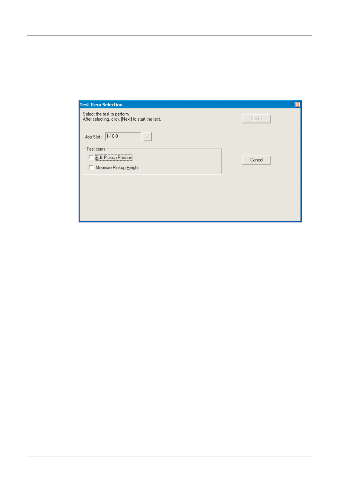
9. Select the type of tests which are to be performed in the newly displayed section. If the
[Edit Pickup Position] option is selected, proceed to the next step. If the [Measure
Pickup Height] option only is selected, then proceed to step 14.
Note: Because the pickup height measurement uses pickup pressure control, the height
measurement test is not possible using heads which have no pressure check sensor. In
such cases, the "Measure pickup Height" item cannot be selected.
NXTEJM013Ea
QD004-18 6. Editing Jobs on the Machine (MEdit)
NXT Programming Manual 179
Checking and editing the X- and Y-positions in the feeder.
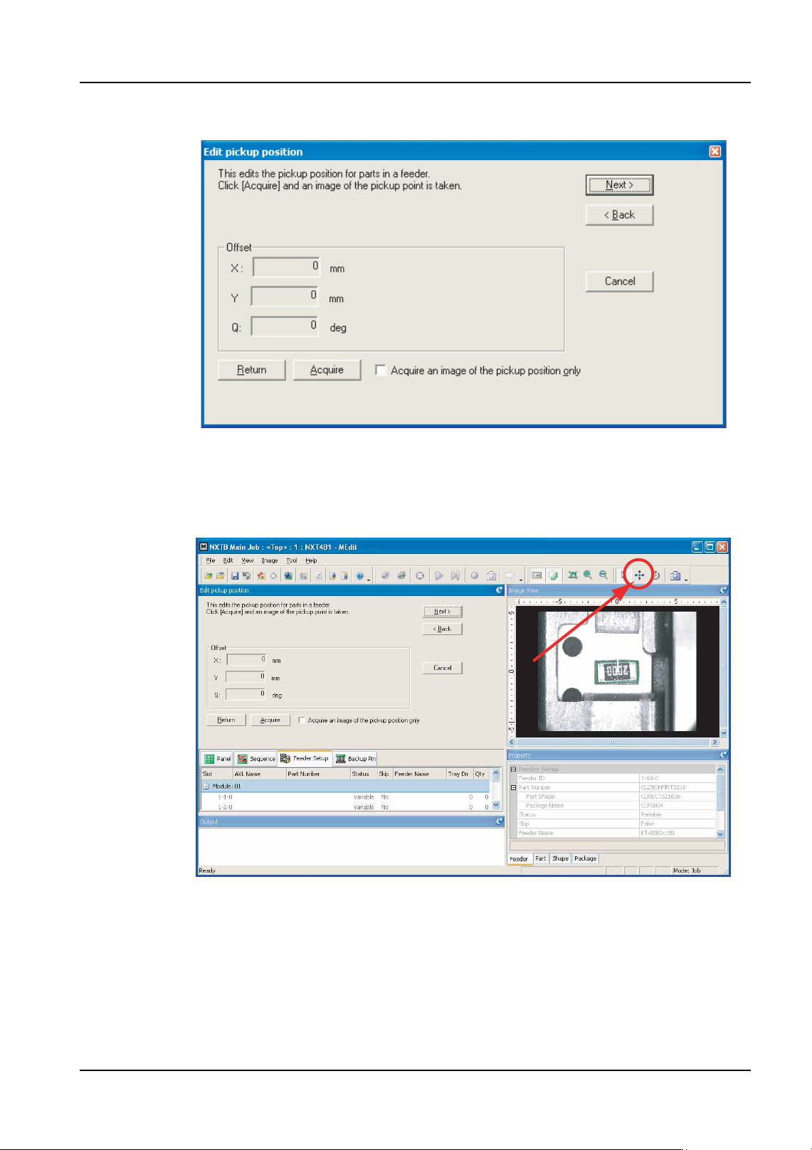
10.The [Edit pickup position] step is displayed. Ensure that the part has been advanced to
the proper position (refer to section 6.8.4 "Feeder index count and tape return method
for pickup tests") then click [Acquire] to take a picture of the part in the feeder. A picture
of the part is taken and displayed.
11.Check the pickup position in the X- and Y-direction using the displayed image. To move
the pickup position, click the positioning button (the button with the four arrows) and then
click in the image where the pickup should be performed.
12.When the pickup position for the part is correct, click [Next]. If the pickup height test is
not being performed, go to step 18.
NXTEJM014Eb
NXTEJM015Eb

6. Editing Jobs on the Machine (MEdit) QD004-18
180 NXT Programming Manual
Checking and editing the pickup height for a feeder.
13.The [Measure Pickup Height] step is displayed. Ensure that the part has been advanced
to the proper position (refer to section 6.8.4 "Feeder index count and tape return method
for pickup tests").
14.If it is necessary to specify a particular nozzle (the nozzle that is to be used in the job is
automatically selected), then follow the sub-steps below.
a. Click [...] to specify which nozzle or claw (OF head only) to use for the test.
Note: The machine knows which nozzles and claws are present in the module (if a check has
been performed by the machine). In cases where the job-specified nozzle and claws can
be used for the height measurement, that nozzle and claws are automatically selected.
b. Select the nozzle or claws (OF head only) to be used for the measurement in the
dialog box that is displayed and then click [OK].
Note: If the module has not yet performed calibration and does not know what nozzles and claws
are present in the nozzle station, click [Measure] to have the module check which nozzles
and claws are present.
15.Click [Measure] to begin the pickup height test.
16.The results of the test are displayed and the Z offset is automatically determined. It is
possible to manually edit this value.
Note: A dialog box is displayed when a stroke error occurs. Click [Yes] in this dialog box to try
moving the head back down and measure again. The same error occurs if there is no part
in the pickup position. If unsure if a part is present or not, check the part status in the feeder.
Caution: If measurement is performed for an OF head, even if the nozzle (claw) does not contact a
part when lowered, the lowest position of the Z-axis is displayed as the result of
measurement. Then, if measurement is performed again, the nozzle (claw) lowers to a
position that is -1.5 mm lower than the result for the previous measurement, so the
measurement value will change greatly. The position at which the result obtained is
approximately the same as the previous result is the position at which the part has actually
been contacted. Due to this, the measurement should be repeated until the result is
approximately the same.
17.Once the Z offset has been determined and the results are acceptable, click [Next].