FUJI NXT Programming Manual QD004-18.pdf - 第42页
3. Job Builder QD004-18 32 NXT Programming Manual 3.3.5 Assigning an alternate feeder The method for assigning a fixed alternate feeder for an NXT-series is di fferent than other Fuji machines. For other machines, an alt…
QD004-18 3. Job Builder
NXT Programming Manual 31
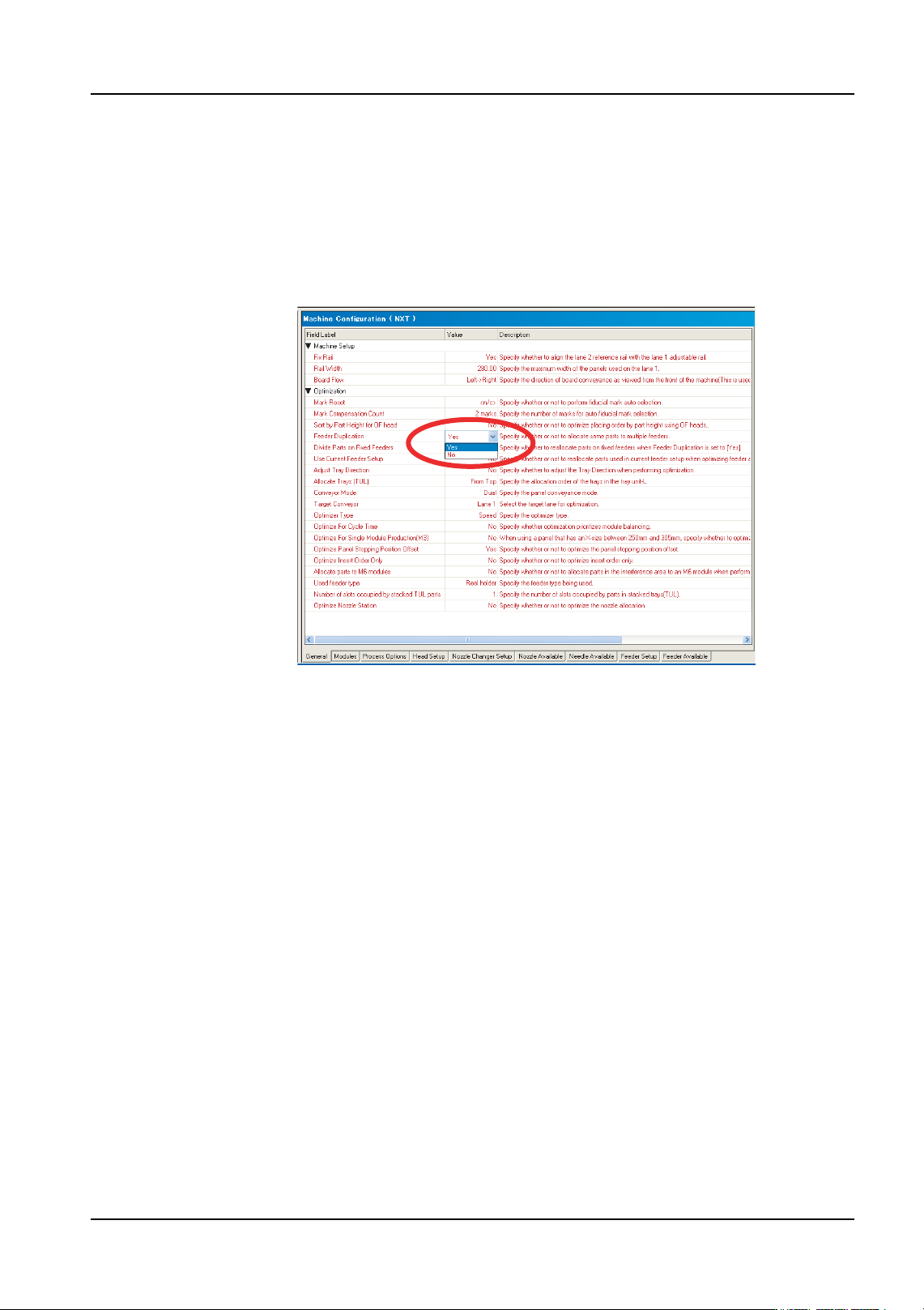
3.3.4 Distributing the same part to multiple modules
1. There are several tabs at the bottom of the [Machine Configuration] pane. Select the
[General] tab.
2. Click the data cell for [Feeder Duplication] in the [Optimization] to display a drop-down
list.
3. Select “Yes” to distribute high part count parts to multiple modules.
4. Optimize the job for the changes to take effect. Parts that have “Yes” specified for [Allow
Multiple Slots] in their part data settings and can be placed on more than one module
are possibly distributed to modules with a compatible configuration by the optimizer.
01PRG-0061E

3. Job Builder QD004-18
32 NXT Programming Manual
3.3.5 Assigning an alternate feeder
The method for assigning a fixed alternate feeder for an NXT-series is different than other
Fuji machines. For other machines, an alternate feeder loop has to be created while for the
NXT an extra feeder with the part is just added to the module. The NXT automatically uses
this extra feeder as an alternate feeder and a loop does not have to be created. It is not
possible to specify which feeder is to be used next for the NXT if there are two or more
alternate feeders as this is decided by the machine. If using Fujitrax Verifier, use the
dynamic alternate feeder function instead.
1. Select the [Top] or [Bottom] tab from the job information bar depending on which side of
the panel the machine is located for which the configuration data needs to be edited.
2. Double-click the name of the line to display the machines in that line.
3. Double-click the name of the NXT machine to set the configuration file for to display the
items for that machine.
4. Double-click [Configuration] under the machines name and a window displays in the
data area.
5. There are several tabs at the bottom of the [Machine Configuration] pane. Click the
[Feeder Setup] tab.
6. Select the module for which the alternate feeder is to be added.
7. Select the feeder position in which to add the alternate feeder by selecting the gray
extreme left cell of that row for the feeder.
8. Right-click and select [Add Feeder] from the shortcut menu and the [Add Feeder] dialog
box is displayed.
9. Select the part for which this feeder is to be the alternate feeder from the drop-down list
and click [OK]. The extra feeder is added and the NXT uses this extra feeder as an
alternate feeder.
QD004-18 3. Job Builder
NXT Programming Manual 33
3.4 Job Settings for Advanced Functions
3.4.1 Setting auto backup pins
This is used with the optional automatic backup pin function on the NXT. It is necessary to
have Fuji Flexa V1.5.1 or higher and NXT control software V3.11 or higher in order to use
this function. In addition, if the NXT does not have this option, then any settings made
regarding this are ignored by the machine.
Cautions when using auto backup pins
• When dual lane production is being performed and a panel exists in only one
lane (either lane 1 or lane 2), the backup pin cannot be positioned or returned
at the lane without a panel. It is necessary to remove panels from both lanes
before positioning or returning backup pins.
• When the job is changed from paired module production to single module
production, backup pins which have been positioned in areas that are
accessible only during paired module production cannot be returned to the
stocker. Therefore, it is necessary to return the pins to the stocker or to change
the backup plates before changing the job. Also, backup pins are automatically
returned to the stocker when the automatic job changeover function is being
used.
• When the panel position correction function is being used, do not position
backup pins at the panel edge detection area when creating the job.
• When using felt paper, do not position backup pins on the felt paper when
creating the job.
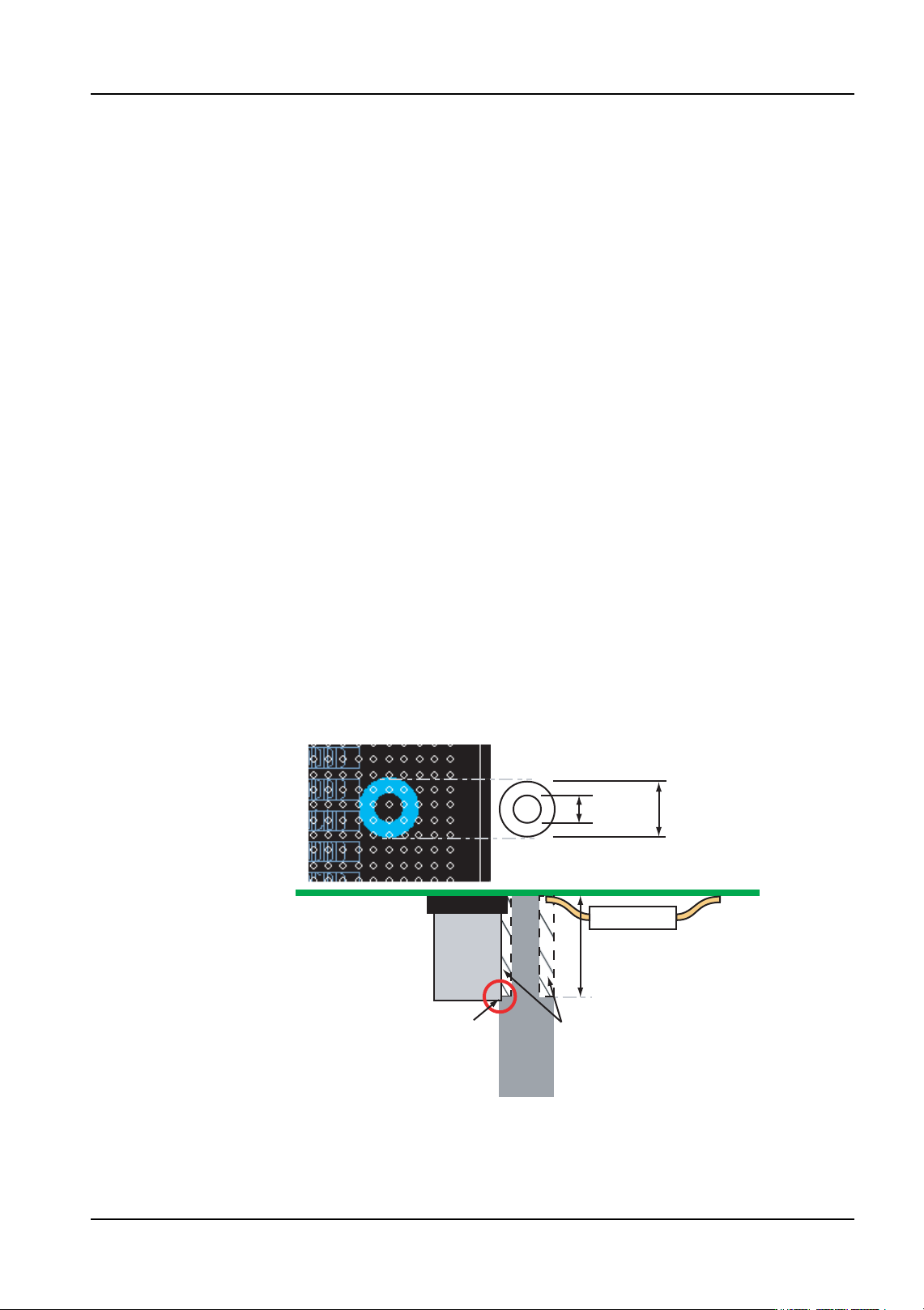
• The display in the Fuji Flexa indicates the possible interference area for tall
parts. Refer to the diagram below.
3.0 mm
6.0 mm
Backup
Pin
Base
Possible interference areas
10 mm
Pin
Pin
Interference
01PRG-0062E