FUJI NXT Programming Manual QD004-18.pdf - 第125页
QD004-18 4. Part Data Settings NXT Programming Manual 115 4.6 Vision Type Details 4.6.1 Part reference point The part reference point is defined as th e point on the part that is aligned with the placing coordinate s on …
4. Part Data Settings QD004-18
114 NXT Programming Manual
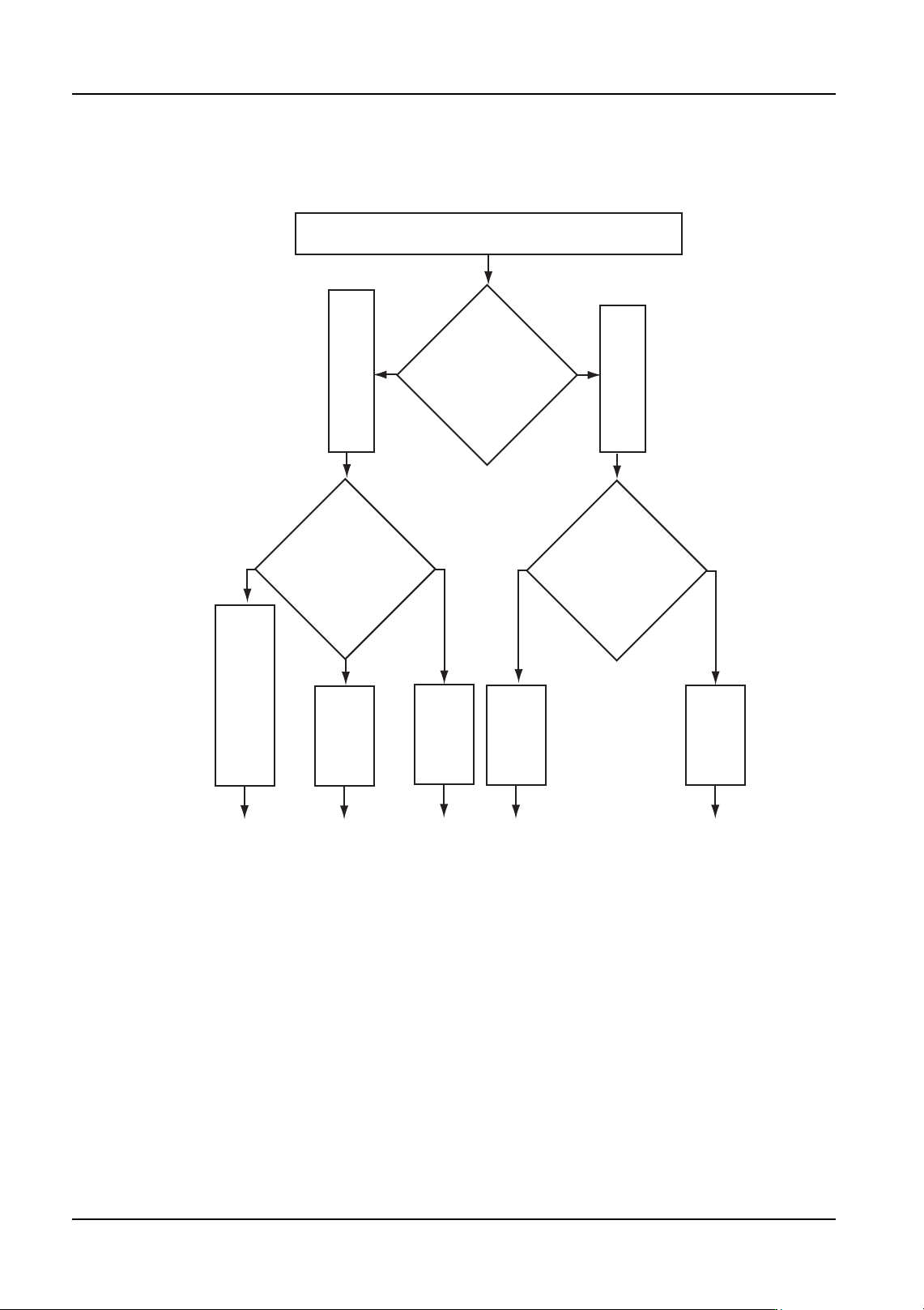
For backlight leaded parts (not supported by the NXT)
NXTVPP023
Lead length direction
and edge status
2 Opposing sides,
1 side only
2 Perpendicular sides,
3 or 4 sides
P_pattern:
3
Leads extend
out of
the body
P_pattern:
5
Leads extend
into the body
Vision Type for a leaded part is selected.
Element
positioning
P_pattern:
13
P_pattern:
11
P_pattern:
15
Lead length direction
and edge status
Leads extend
out of
the body
Leads extend
into the body
Lead detection is unstable,
or both ends of the leads
are attached to the body.
QD004-18 4. Part Data Settings
NXT Programming Manual 115
4.6 Vision Type Details
4.6.1 Part reference point
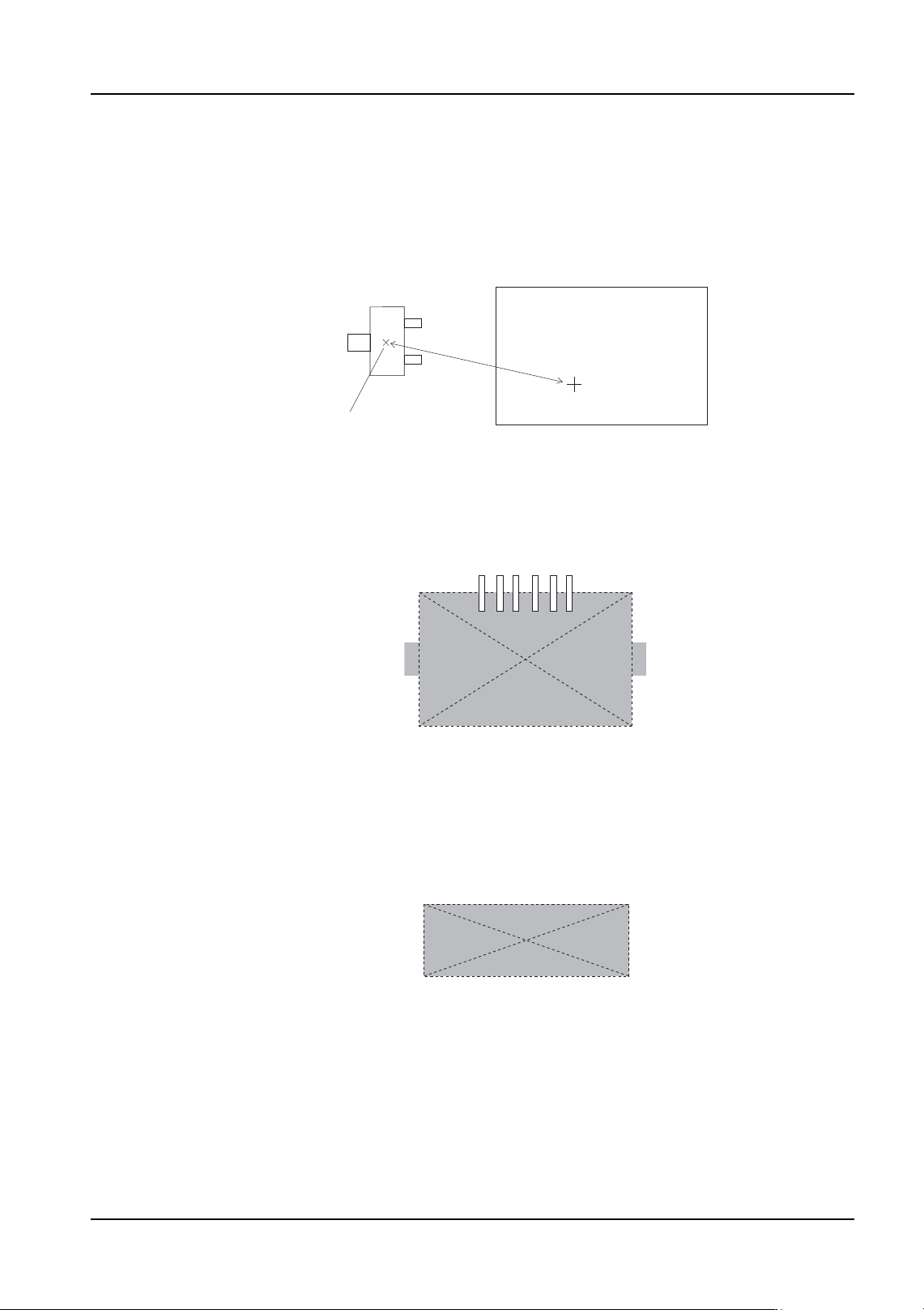
The part reference point is defined as the point on the part that is aligned with the placing
coordinates on the panel when the part is placed.
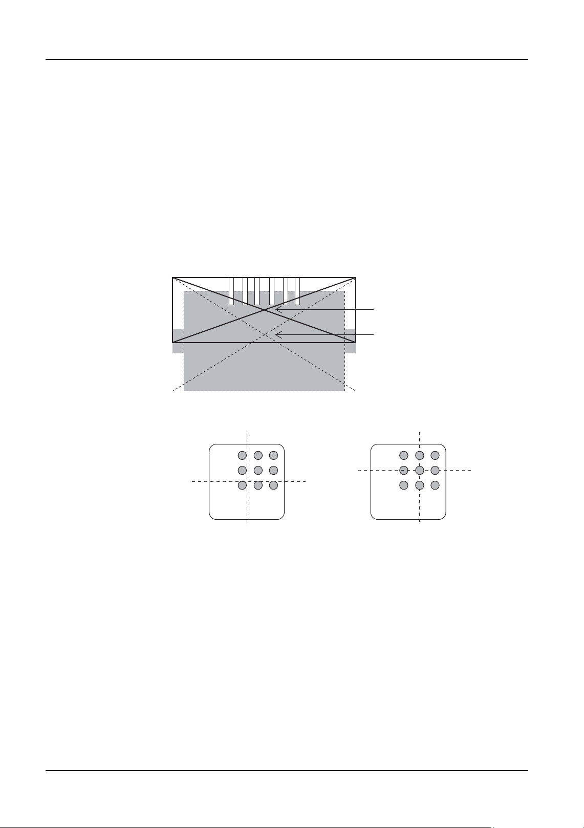
Body center
The center is taken from the outer-most points of the body; top, bottom, left, and right.
(The leads have no affect on the placing coordinates.)
Part center
The part center is defined as follows.
1. Part center of non-leaded parts
The part center is taken from the outer-most points; top, bottom, left, and right.
2. Part center of parts with leads (ball grids)
The part center is calculated from the coordinates of the lead ends or from the center
coordinates of the ball grid taken from the outer-most points; top, bottom, left, and right.
The point of intersection of the center line from the outer-most points top to bottom and
the center line from the outer-most points left to right yields the part center. However, if
there are leads or a ball grid on only one side, a theoretical part center is defined based
on the part data.
The following combinations are possible based on the lead positions.
Part
Placing coordinates (X, Y)
Panel
Reference point
Match
4. Part Data Settings QD004-18
116 NXT Programming Manual
• Leads on only one side
• Leads on two opposite sides
• Leads on two adjacent sides
• Leads on three sides
• Leads on four sides
The center moves depending on the lead positions, lead lengths, and lead widths.
For parts with leads on three sides, the part center is defined as the point of intersection of
the center line from the outer-most points top to bottom and the center line from the outer-
most points left to right. As a result, the part center required for placement differs from the
actual placing position.
Ball grid body center and part center
Calculated part center
Theoretical part cente
r
Part reference point: body center
Part reference point: part center