FUJI NXT Programming Manual QD004-18.pdf - 第34页
3. Job Builder QD004-18 24 NXT Programming Manual Placing Procedure Mark Read Procedure Use Auto Backup Pin Specify whether or not to u se auto backup pins. Yes: Use auto backup pins. No: Do not use auto backup pins. Set…
QD004-18 3. Job Builder
NXT Programming Manual 23
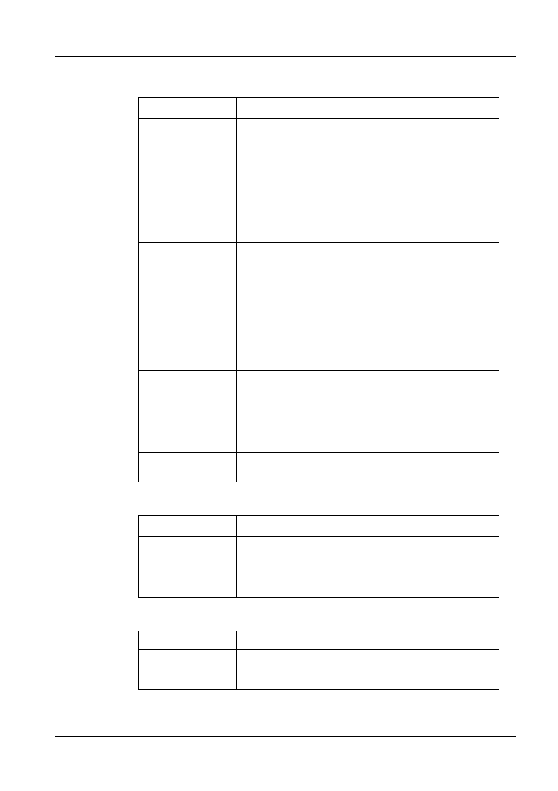
Panel Conveyance
Glue
Backup Plate
Setting Description
Speed Specify the panel conveyance speed.
High: This speed can convey panels with standard parts in
a stable manner.
Middle: This conveys panels at 70% of the high speed.
Low: This conveys panels at 50% of the high speed.
ULow: This conveys panels at 30% of the high speed.
Decelerate Module
No.
Specify the module number from which the panel
conveyance speed is slower after exiting the module.
Speed After
Decelerate
Specify the panel conveyance speed for panels after they
exit the module from which the slower conveyance was
specified. This must be a slower setting than that specified
in [Speed].
Middle: This conveys panels at the same speed as the
Middle setting for Speed.
Low: This conveys panels at the same speed as the Low
setting for Speed.
ULow: This conveys panels at the same speed as the
ULow setting for Speed.
Clamp Torque Specify the clamp torque when panels are clamped. This
is only applicable for conveyors that use motors to clamp
the panel, such as the single conveyor S.
Normal: Normal torque
Soft: Light torque (Used when placing parts on fragile
panels.)
Bottom Side Part
Height
Specify the height of parts on the bottom side of the panel.
The transport speed can be increased for shorter parts.
Setting Description
Do Apply Check Specify whether or not to glue check sequences are
applied to check the glue condition.
Yes: Place glue check sequences and check
No: Do not check
Setting Description
Backup Plate Name Specify the back-up plate name. This is optional and is
used to indicate a specific backup plate when performing
changeover.
3. Job Builder QD004-18
24 NXT Programming Manual
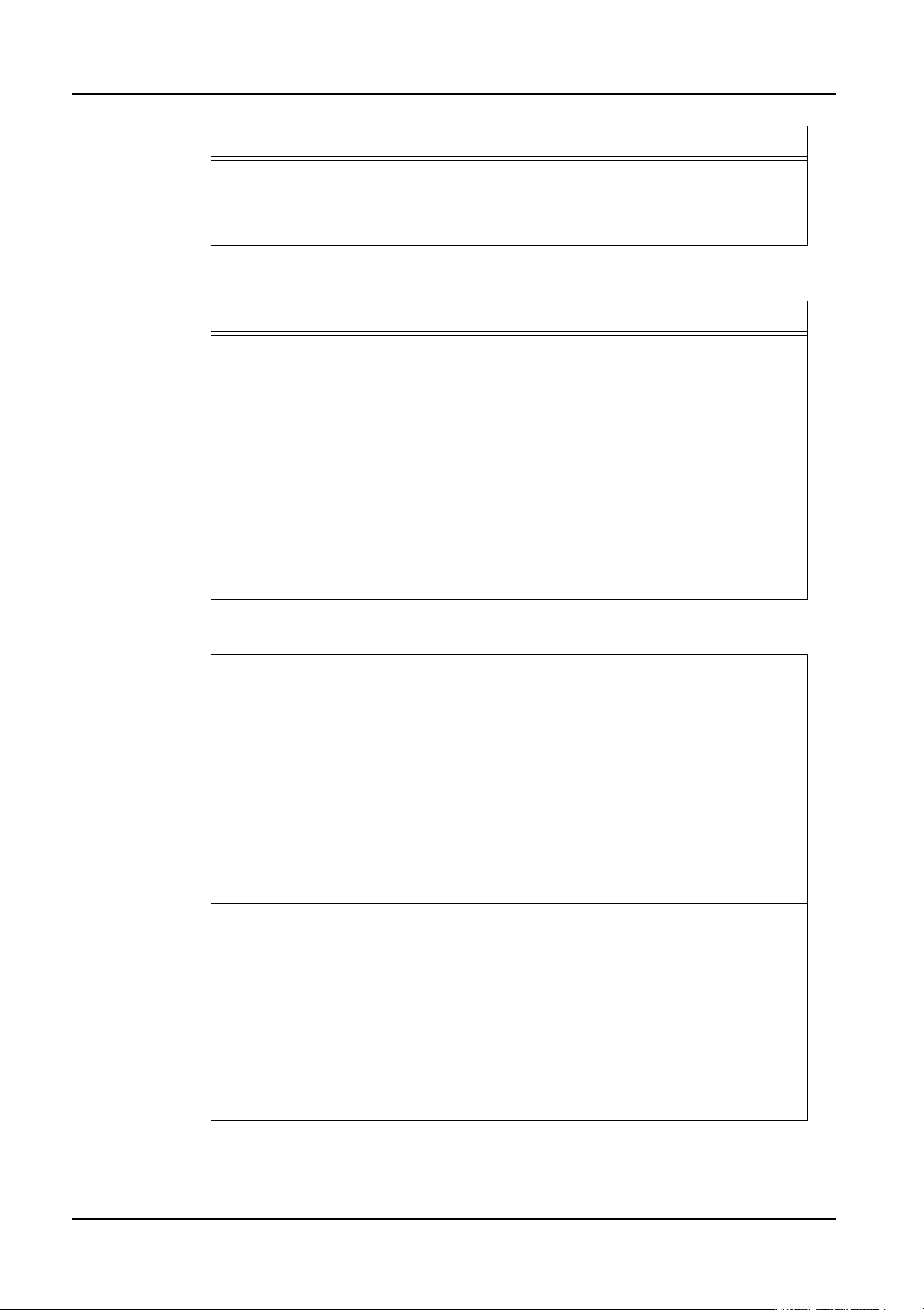
Placing Procedure
Mark Read Procedure
Use Auto Backup
Pin
Specify whether or not to use auto backup pins.
Yes: Use auto backup pins.
No: Do not use auto backup pins.
Setting Description
Placed Parts Height Specify the height of premounted parts on panels received
from the previous machine.
Because the maximum allowable height varies depending
on the head types in NXT and AIM machines, the lowest
allowable height value for all of the modules/heads is used
for the entire machine.
Head type: Maximum allowable height
H01, H02, OF: 25.4 mm
H04: 9.5 mm
F04, G04: 6.5 mm
H08: 6.5 mm
H12, H12S: 3.0 mm
GL: 7.0 mm (Stroke Height: 12.0 mm), 3.0mm (Stroke
Height: 8.0mm), 0.0mm (Stroke Height: 6.0mm or less)
Setting Description
Area Tolerance When marks are read, the current and previous mark
reading results are compared to determine if an object was
incorrectly recognized as a mark. The width of the
deviation between the previous and current result for each
mark is calculated and compared.
Enter a tolerance value. If there is only deviation in the
panel loading position, most likely there will be little
deviation in width. If the tolerance is exceeded, the
machine determines that a mark has been incorrectly
recognized and an error occurs.
If the tolerance value is 0 mm, tolerance is not checked.
Pitch Tolerance When marks are read, the current and previous mark
reading results are compared to determine if an object was
incorrectly recognized as a mark. The distance between of
the previous and current result for each mark are
calculated and compared.
Enter a tolerance. As long as the panel is not extremely
deformed, most likely there will be little deviation in the
distance between marks. If the tolerance is exceeded, the
machine determines that a mark has been incorrectly
recognized and an error occurs.
If the tolerance value is 0 mm, tolerance is not checked.
Setting Description
QD004-18 3. Job Builder
NXT Programming Manual 25
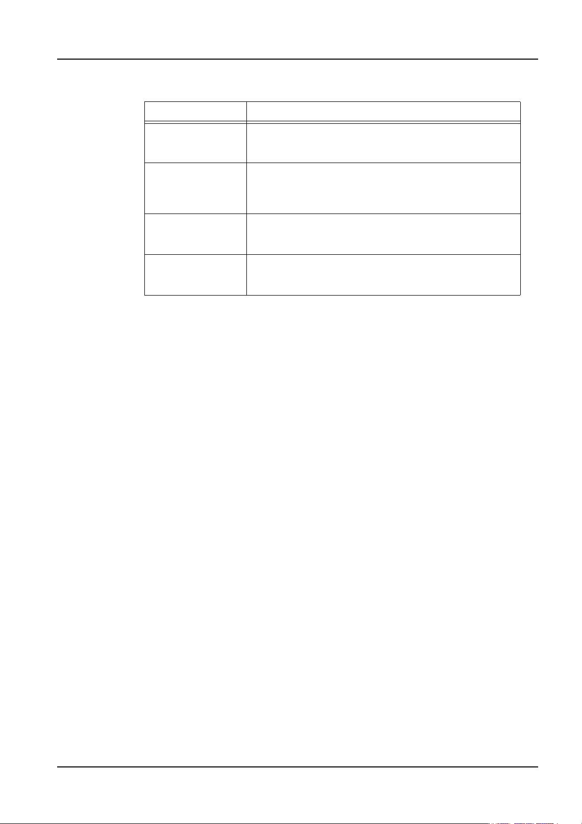
Panel Stopping Position Correction
The new settings will take effect the next time the job is transmitted to the machine or
optimization is performed.
Specifying the head setup for an NXT
Making settings in the [Head Setup] tab is not normally necessary. The head setup will be
automatically reconfigured based upon the nozzles in the nozzle changer during
optimization.
1. There are several tabs at the bottom of the [Machine Configuration] pane. Select the
[Head Setup] tab.
2. Use the [Module] drop-down list to select the desired module to display.
3. Click the [Name] field in the nozzle table and then the arrow to display a drop-down list
of the available nozzles. Click to select the desired nozzle for that position.
Note: It is possible to specify nozzles for multiple positions at a time. Select the multiple nozzle
positions for the head and then right-click in the window. Select [Select Nozzles] and then
select the desired nozzle for the selected positions from the drop-down list and click [OK].
Setting Description
Scan Area X/Y This specifies the size of the area in the X- and Y-direction
checked for the panel edge when correcting the panel
stopping position.
Shutter Speed This setting specifies the shutter speed used by the mark
camera when checking for the panel edge. The larger the
value, the slower the shutter speed and the image
becomes brighter.
Color Specify which lighting should be used to check for the
panel edge. Different settings will be required depending
on the color of the panel.
Pattern Specify which lights should be used to check for the panel
edge. Different settings will be required depending on the
color of the panel.