FUJI NXT Programming Manual QD004-18.pdf - 第134页
4. Part Data Settings QD004-18 124 NXT Programming Manual Vision Type 80 Round shaped parts Enter only the body size in part da ta. There is no need to enter element information. The reference point for th e part is th e…
QD004-18 4. Part Data Settings
NXT Programming Manual 123
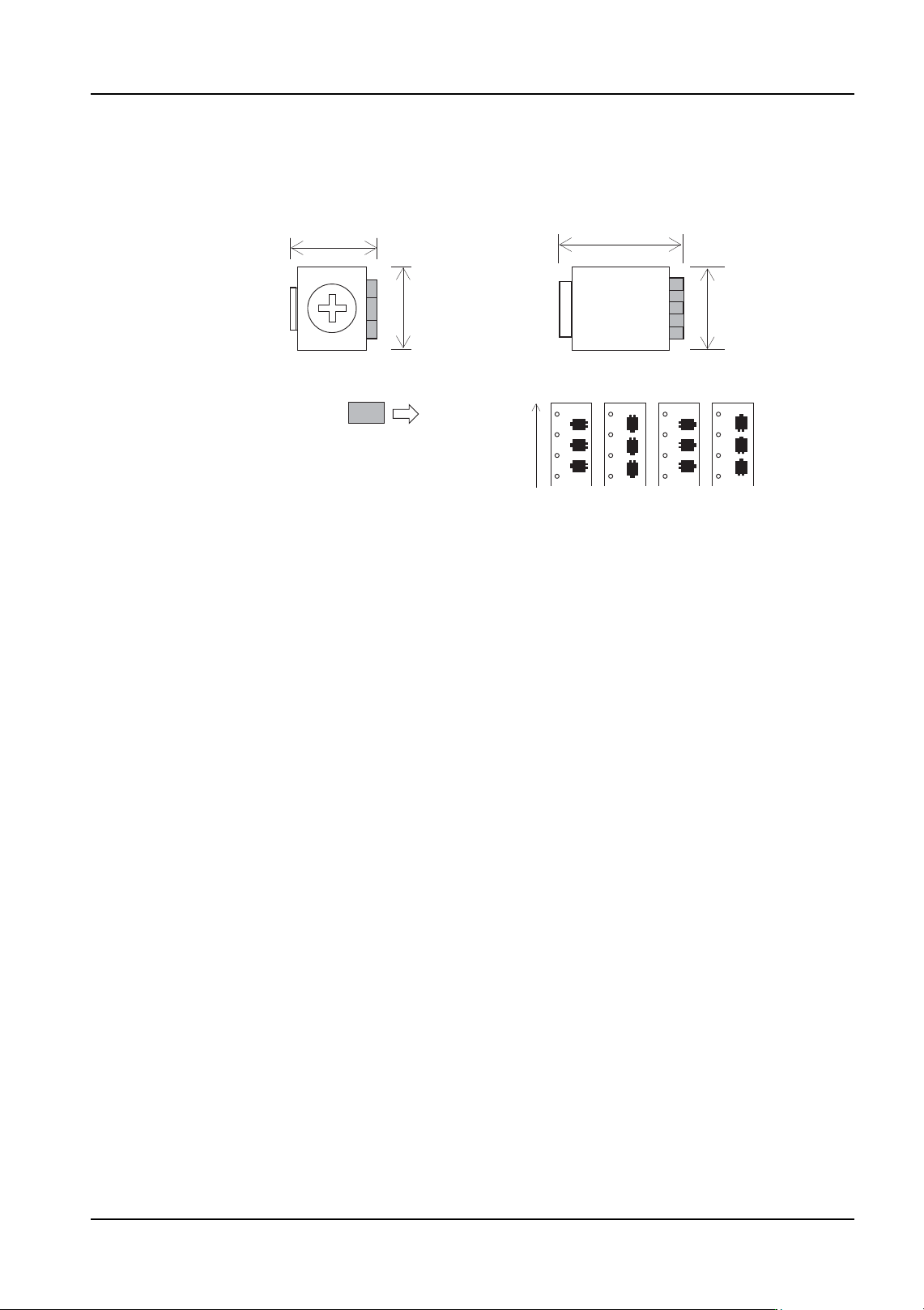
Vision Type 74 Trimmer resistors, trimmer capacitors (Polarity check performed)
It is necessary to enter the body size and element information in part data.
Enter the lead quantity (2 or 3), lead width and length, and width tolerance.
First, the part position is determined using the vision type 71 processing method, and then,
direction inspection is performed based on the detection of one lead. However, the
detected lead is not used for positioning. The reference point for the part is the part center.
It is important to note the following points.
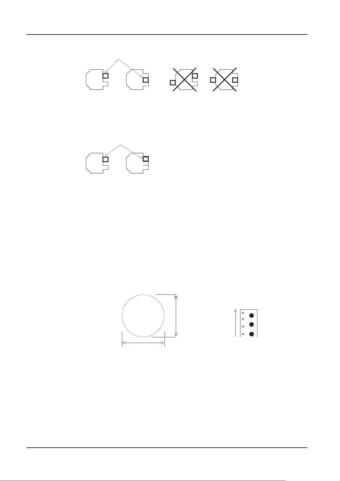
• Direction inspection is possible only if there are 2 or 3 leads on only one side.
• Direction inspection cannot be performed if diagonally across from the detected
lead there is a protrusion of the same shape as the lead. (Fig. 1 on the next
page)
• Using a two pin setting, detection of three pins of the same shape is not possible.
(Fig. 2 on the next page)
• Only enter one element into the element information. If 2 or more elements are
entered, an 0xD62A error (element data is incorrect) occurs when the parts are
being registered.
Direction 0 deg 90 deg 180 deg 270 deg
Supply direction
Body size X
Body size X
Body
size
Y
Body
size
Y
Trimmer resistors
Trimmer capacitors
Element
4. Part Data Settings QD004-18
124 NXT Programming Manual
Vision Type 80 Round shaped parts
Enter only the body size in part data. There is no need to enter element information. The
reference point for the part is the part center.
2-pin 3-pin
Fig. 1 Detected lead position when performing direction inspection
Detected lead
Direction inspection is impossible if
a protrusion of the same shape as the lead exists
diagonally across from a lead.
Fig 2. Set as 2-pin part in part data
Detected lead
2-pin 3-pin (no error occurs)
Direction 0 deg
Supply direction
Body size Y
Body size X
Round shaped part
QD004-18 4. Part Data Settings
NXT Programming Manual 125
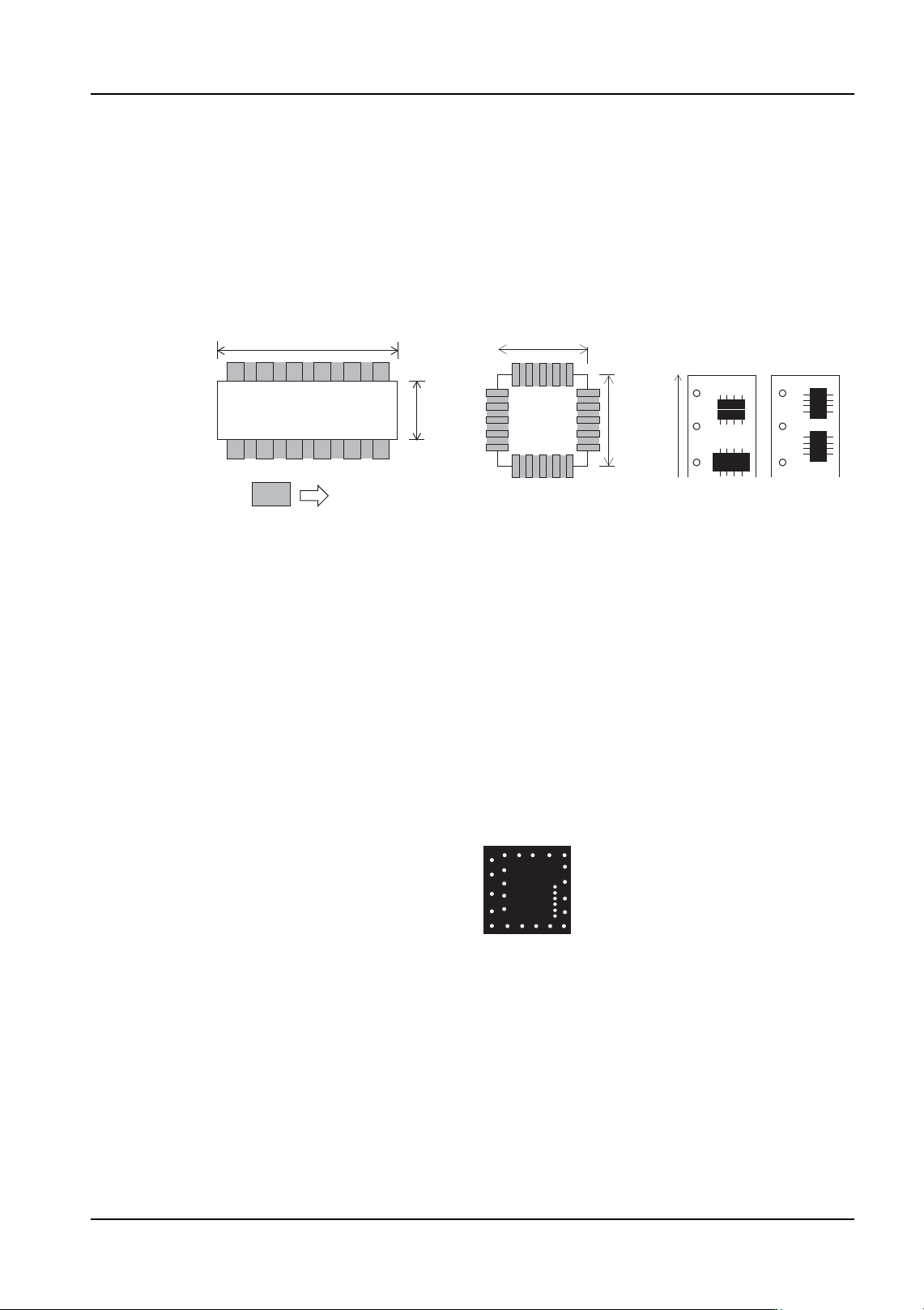
Vision Type 123 (128) IC- type leaded parts
Vision Type 124 (129) J-leaded parts
Enter the body size and element information in part data. Due to the use of frontlighting,
there are cases in which the acquired image may vary depending on the shape of the leads
and the lighting conditions. In such cases, it may be necessary to make adjustments to the
position, length and width of the lead information in element information. Vision types 123,
124 use the body center while vision types 128, 129 use the part center.
Vision Type 140 (145) Flip-chips
Enter the body size and element information in part data. Vision type 140 uses the body
center while vision type 145 uses the part center.
Due to the use of frontlighting, there are cases in which the image of the ball grid may vary
depending on the shape of the leads and the lighting conditions. In such cases, it may be
necessary to make adjustments to the ball grid position, length and width of the lead
information in element information.
Inspection of certain parts may not be possible due to variations in the body color and the
and the image of the ball grid.
SOIC
Direction 0 deg 90 deg
Element
Body
size
Y
Body size X
Supply direction
PLCC
Body size X
Body
size
Y
Flip chip