FUJI NXT Programming Manual QD004-18.pdf - 第119页
QD004-18 4. Part Data Settings NXT Programming Manual 109 P_pattern 15, 16 Basically, these are the same as p_pattern typ es 5 and 6. The major difference is that with these p_patterns, the inward pointing lead tip is no…
4. Part Data Settings QD004-18
108 NXT Programming Manual
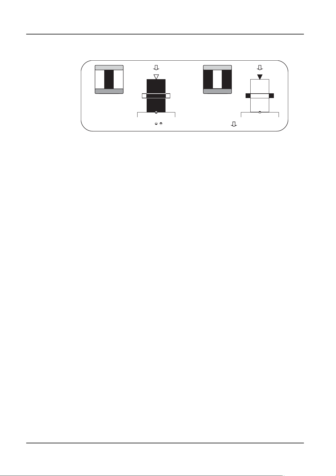
P_pattern 13, 14
Basically, these are the same as p_pattern types 3 and 4. The major difference is that with
these p_patterns, the outward pointing lead tip is not used for determining the part
positioning. The lead width detection results only are used to determine the part
positioning. The lead tip detection results are used only as reference data for internal vision
processing items.
• Type 13: The lead appears black and the outside circumference is white.
• Type 14: The lead appears white and the outside circumference is black.
It is only possible to use this for parts that have leads that are to be detected on two
perpendicular sides or more.
Furthermore, the information for the part positioning using the lead length is not acquired
so these types cannot be used for parts with leads on one side or two opposing sides only.
Example Target Parts
Type 13: QFP parts processed with backlighting.
Type 14: Black background and body parts (e.g., QFP) processed with frontlighting.
NXTVPP017E
:Entered element position
:Defined element direction
Type 13 Type 14
QD004-18 4. Part Data Settings
NXT Programming Manual 109
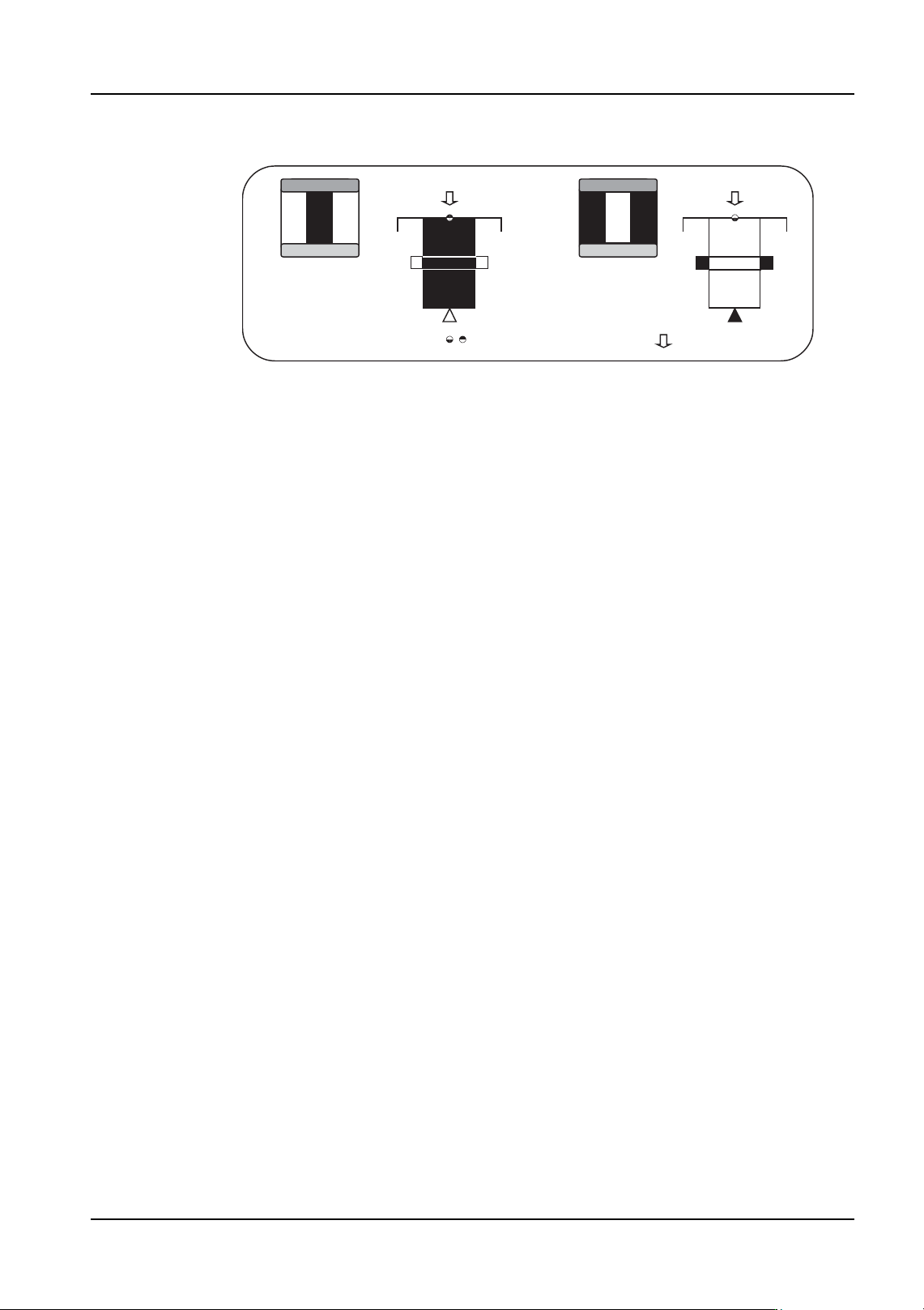
P_pattern 15, 16
Basically, these are the same as p_pattern types 5 and 6. The major difference is that with
these p_patterns, the inward pointing lead tip is not used for determining the part
positioning. The lead width detection results only are used to determine the part
positioning. The lead tip detection results are used only as reference data for internal vision
processing items.
• Type 15: The lead appears black and the outside circumference is white.
• Type 16: The lead appears white and the outside circumference is black.
It is only possible to use this for parts that have leads that are to be detected on two
perpendicular sides or more.
Furthermore, the information for the part positioning using the lead length is not acquired
so these types cannot be used for parts with leads on one side or two opposing sides only.
Example Target Parts
Type 15:Currently no example target part exists.
Type 16:Black background and body parts with orthogonal leads in the body (e.g., LCC)
processed with frontlighting.
NXTVPP018E
:Entered element position
:Defined element direction
Type 16 Type 15
4. Part Data Settings QD004-18
110 NXT Programming Manual
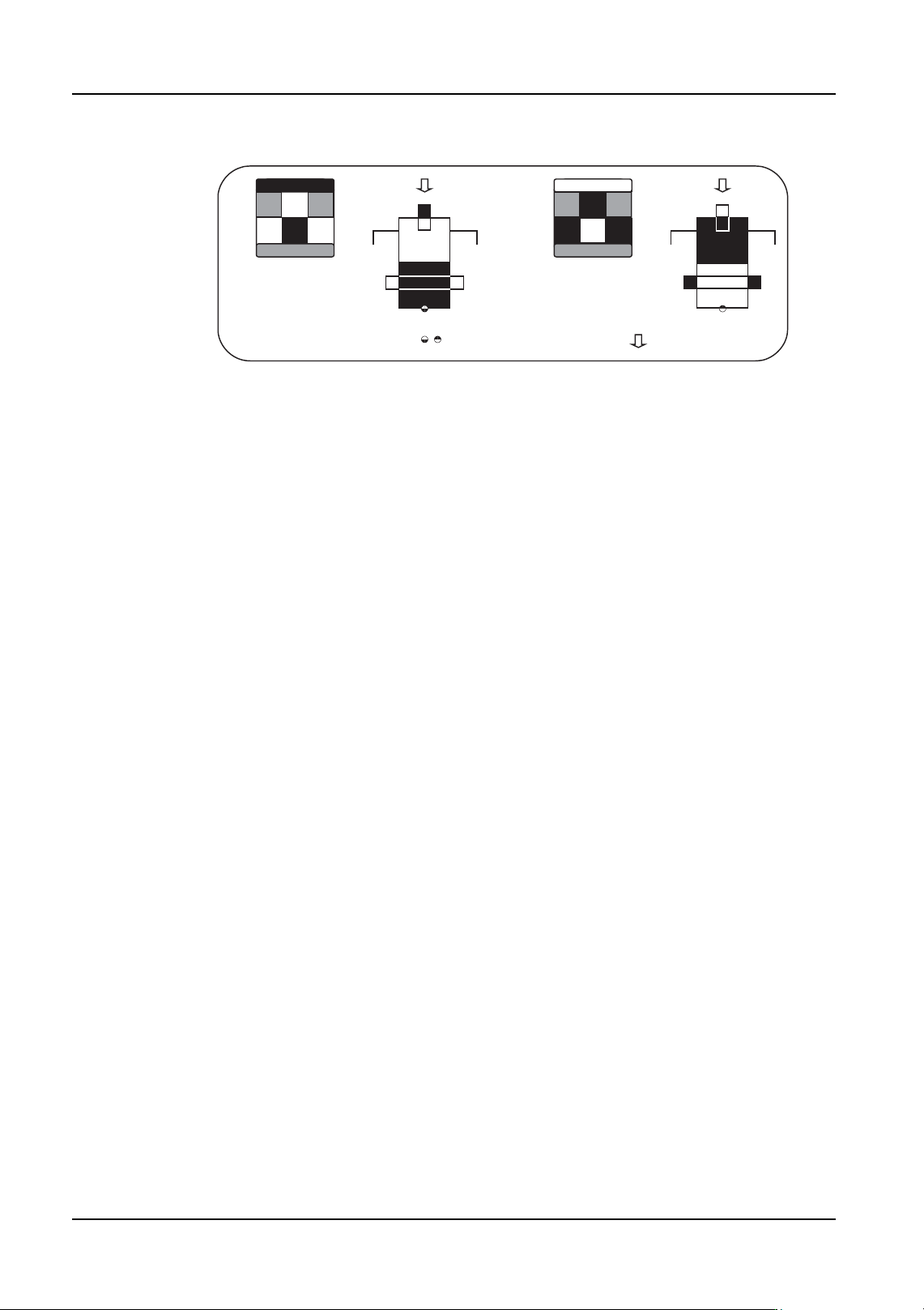
P_pattern 23, 24
These cannot be used on the NXT. The lead tip and width are detected and the results are
used to determine the part position similar to p_pattern types 3 and 4. The major difference
is that with these p_patterns, the color of the points on the lead at which the lead tip and
lead width are detected are opposite.
• Type 23: The lead tip appears white, while the lead body appears black. The
lead tip half of the outside circumference is black, while the body half is white.
• Type 24: The lead tip appears black, while the lead body appears white. The
lead tip half of the outside circumference is white, while the body half is black.
These are primarily used for parts with J-leads on one side or two opposing sides.
With parts that have J-leads on two perpendicular sides or more, the lead width direction is
only required for determining the positioning, therefore it is recommended to select a
different p_pattern (type: 33, 34) that matches the processing conditions.
Example Target Parts
Type 23: Currently no example target part exists.
Type 24: SOJ parts processed with frontlighting with a white background.
NXTVPP019E
:Entered element position
:Defined element direction
Type 23 Type 24