FUJI NXT Programming Manual QD004-18.pdf - 第94页
4. Part Data Settings QD004-18 84 NXT Programming Manual Entering part dimensions and positions The dimensions a nd positions for the part are entered in the X- and Y-directi ons when viewed from above. FUJI Y X XY-coord…
QD004-18 4. Part Data Settings
NXT Programming Manual 83
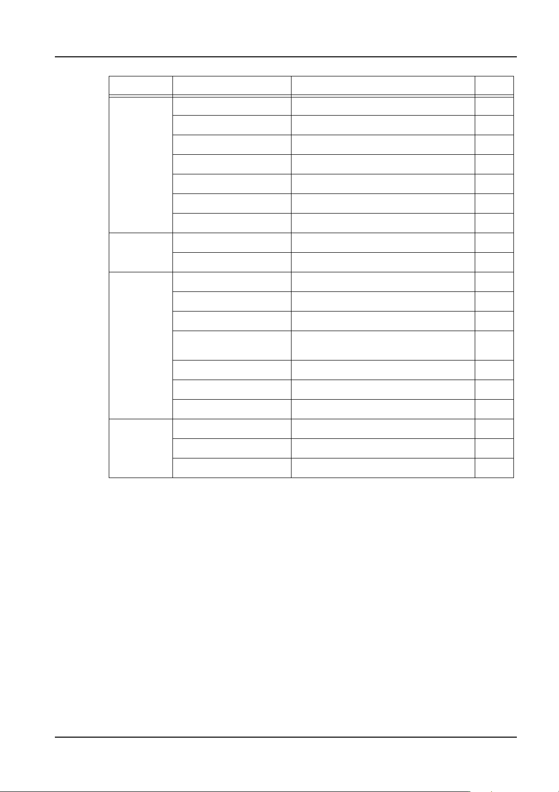
Settings that have blank comments have the same explanation and settings for multiple Fuji
machine types. Settings with the vision related comment affect the vision processing.
The settings for items with an O in the “Chg” column can be changed in MEdit. The settings
for items with an X in this column cannot be changed in MEdit. N/A means that this part
data setting is not set at the machine so any changes here are not reflected at the machine.
Pin Check Pin Check Mode X
Is Bottom Mark Present X
Is Bump Present X
Upper Left X X
Upper Left Y X
Lower Right X X
Lower Right Y X
Coplanarity Do Coplanarity Coplanarity check related setting. X
Coplanarity Editor Coplanarity check related setting. X
Flux Do Flux X
Dwell Time O
Slow Dipping Height O
Slow Dipping Down
Speed
O
Slow Dipping Up Speed O
Squeegee Height O
Do Dipping Check O
Solder
Paste
Do Check O
High Brightness O
Low Brightness O
Section Name Comments Chg
4. Part Data Settings QD004-18
84 NXT Programming Manual
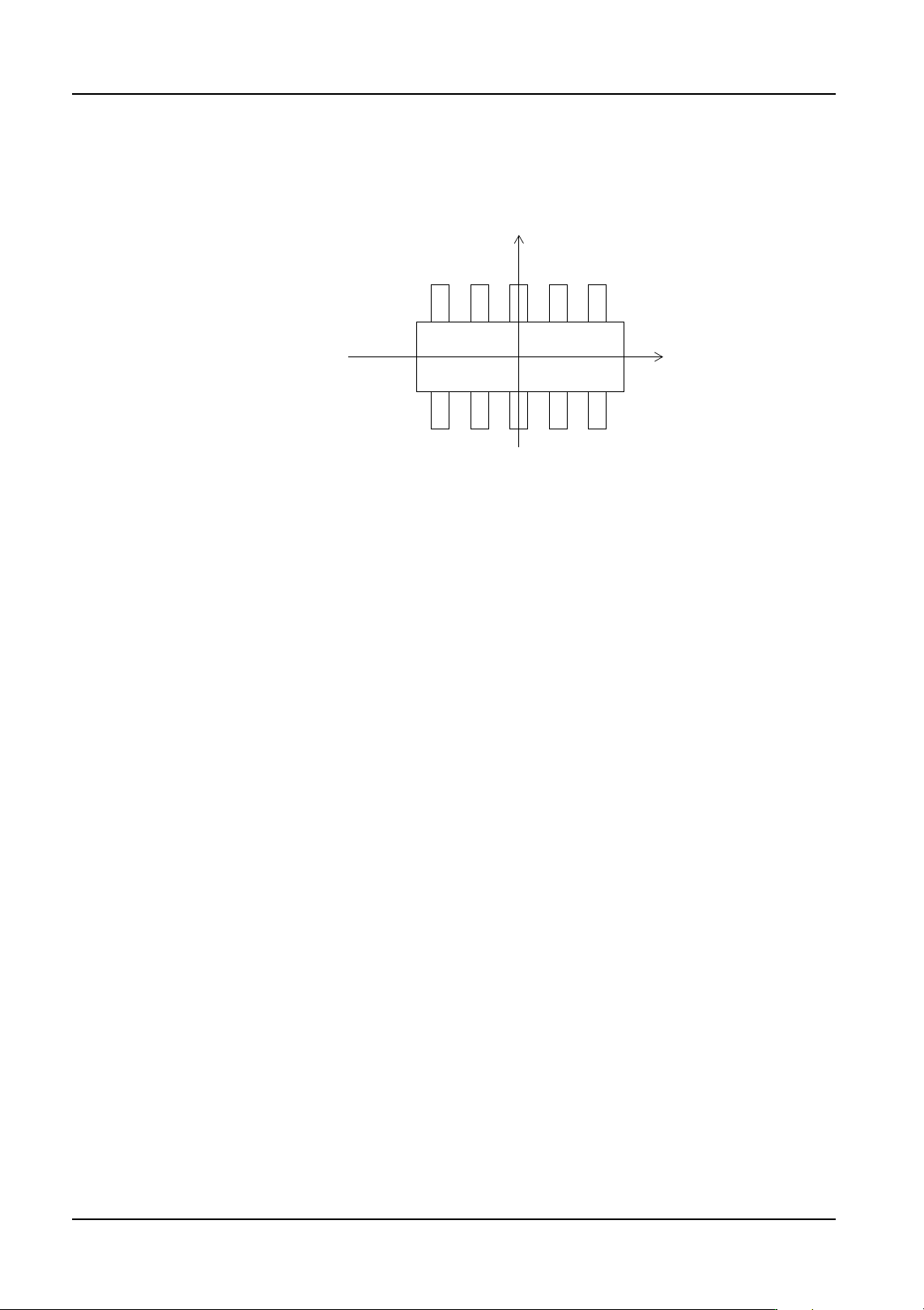
Entering part dimensions and positions
The dimensions and positions for the part are entered in the X- and Y-directions when
viewed from above.
FUJI
Y
X
XY-coordinates (part upper surface)
+
+

QD004-18 4. Part Data Settings
NXT Programming Manual 85
4.3.3 Shape Information details
Body
Length (X)
Specify X-direction length of the part's body size.
Width (Y)
Specify Y-direction length of the part's body size.
Length Tolerance (X)
Specify the part's X-direction length tolerance.
Width Tolerance (Y)
Specify the part's Y-direction length tolerance.
Height
Specify the part's height.
Height Tolerance
Specify the part's height tolerance.
Color
For the NXT, this is used for vision processing of parts. Parts that are using the body
detection vision types must have the color specified as “White”.
The vision type that this setting must be “White” are: 60, 61, 62, 63, 65, 71, 74, 80, 153,
160, and 252.
Parts using these vision type that do not appear “white” in the images (the body is completly
black with no leads), cannot be vision processed using these vision types.
Lead
Pitch Tolerance
It is the tolerance allowed for the deviation from the pitch as a percentage of the lead pitch
length. If no setting is made here, processing is carried out using a default value of 30%.
Element Information
Set element related data. An element is a group of leads on the same side of a part which
have the same length, width, and pitch. As there may be several elements on a part,
numbers are assigned to the elements for identification purposes.
Double-click the data cell for this field and the [Element Information] dialog box displays.