FUJI NXT Programming Manual QD004-18.pdf - 第140页
4. Part Data Settings QD004-18 130 NXT Programming Manual Vision Type 180 (185) SOT-typ e parts Use this vision type for parts with betwe en 2 and 6 leads where the body color is black and only the leads are visible du r…
QD004-18 4. Part Data Settings
NXT Programming Manual 129
Vision Type 170 Mechanical chuck part existence check
Use this vision type when part recognition is not possible using any other vision type. In the
shape data, set the vision type to 170, specify a setting for [Lead Brightness] and specify
the check area and select either 1 or 2 for the p_pattern in the element information. Based
on this data, if it is determined that the part has been picked, then the part is placed without
performing any correction based on vision. The part is positioned mechanically.
When vision processing is performed, the average greyscale of the area specified in the
element data is determined. This average is compared to the lead brightness setting and
based on the p_pattern setting it is determined whether or not the part is present.
If the p_pattern setting is 1 (dark) and the average greyscale value is higher than the lead
brightness setting, it is determined that the part is present. If the average grayscale is lower
than the lead brightness setting, then it is determined that the part is not present.
If the p_pattern setting is 2 (light) and the average greyscale value is lower than the lead
brightness setting, it is determined that the part is present. If the average grayscale is
higher than the lead brightness setting, then it is determined that the part is not present.
Note: Use a chuck with four claws when using this vision type.
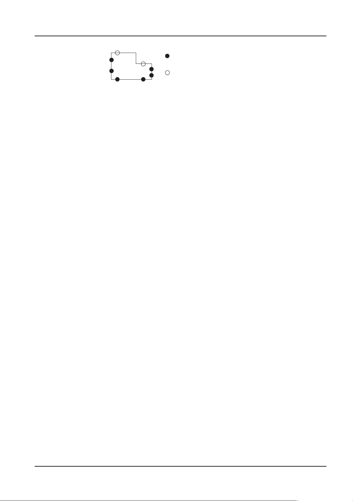
: Points which can be used to define the part body.
: Points which cannot be used to define the part body.
4. Part Data Settings QD004-18
130 NXT Programming Manual
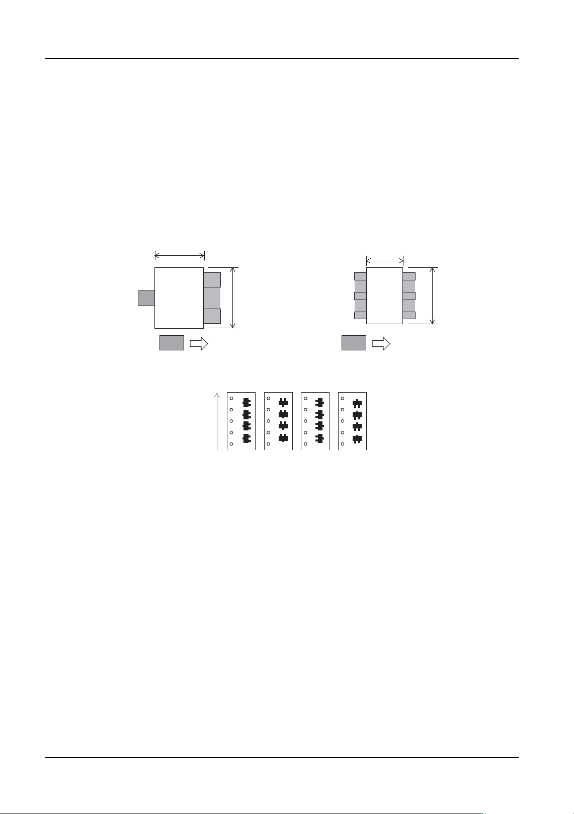
Vision Type 180 (185) SOT-type parts
Use this vision type for parts with between 2 and 6 leads where the body color is black and
only the leads are visible during vision processing. Enter the body size and element
information in part data. Vision type 180 uses the body center while vision type 185 uses
the part center
Note: This vision type can be used for parts with up to six leads. Vision processing is not possible
for parts with 7 leads or more.
Note: Vision processing may not be performed if the lighting is unevenly reflected by leads.
SOT (3 leads)
SOT (6 leads)
Direction 0 deg 90 deg 180 deg 270 deg
Element
Body size X
Body size Y
Element
Supply direction
Body size X
Body size Y
QD004-18 4. Part Data Settings
NXT Programming Manual 131
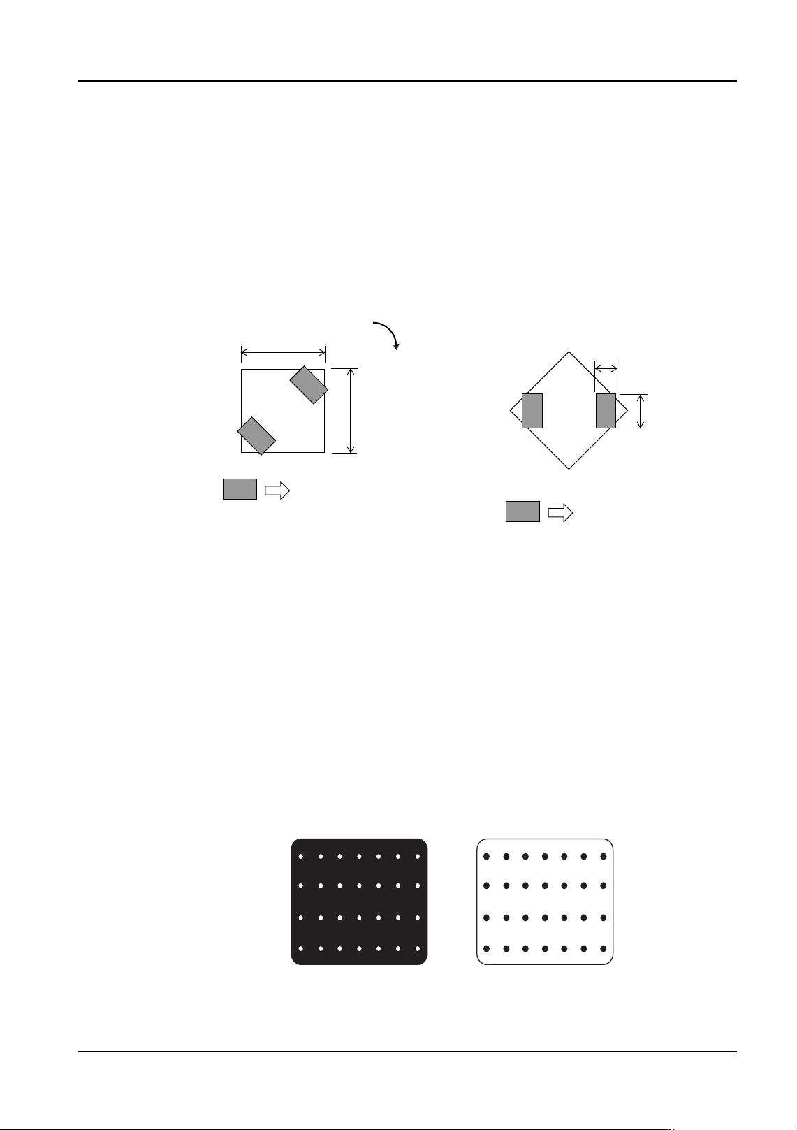
Vision Type 181 Coil parts with two leads at 45 degree angles
Use this vision type for coil parts with 2 leads that are at 45 degree angles from the x-axis
(as shown below). The body color is black and only the leads are visible during vision
processing.
It is necessary to input the following body size and element information.
• The lead elements must be defined as “Side 0” and “Side 2”
• For each element, define the number of leads as [1].
Vision Type 230 (235) Black bodied BGAs
Vision Type 231 (236) White bodied BGAs
Vision Type 233 (238) Black bodied CSPs
Vision Type 234 (239) White bodied CSPs
Enter the part body size and element information in part data. Vision types 230, 231, 233,
and 234 use the body center while vision types 235, 236, 237, and 238 use the part center.
Due to the use of frontlighting, there are cases in which the image of the ball grid may vary
depending on the shape of the leads and the lighting conditions. In such cases, it may be
necessary to make adjustments to the ball grid position, length and width of the lead
information in element information.
Note: For details on parts that contain bumps in a non-symmetrical pattern, refer to vision type
142(147).
Coil in 0 direction
Coil rotated -45 degrees
Body Length (X)
Body Width (Y)
Element
Lead Length
Lead Width
Side 0
Side 3
Side 1
Side 2
Side 0
NXTPRG046Ea
-45 degrees
Element
Black BGA
White BGA