FUJI NXT Programming Manual QD004-18.pdf - 第56页
3. Job Builder QD004-18 46 NXT Programming Manual Settings in shape data Specify that the presen ce of the part is to be checked by specifying the following setting in the shape data (part d ata) for th e part in F uji F…
QD004-18 3. Job Builder
NXT Programming Manual 45
3.4.5 Using the parts presence check function (from NXT V4.42)
Make the following settings in the job before using a head with part presence check sensor
and you want to use this function. Some heads that have the part presence sensor are the
H12SQ, H08Q, H04Q, F04*, G04*, H02, and H01 (for heads with the *, the machine
configuration setting automatically changes when they are selected).
• Fuji Flexa V3.4.0 or later is required.
• Do not use nozzles with a rubber pad when using the part presence check
function with H12SQ, H08Q, H04Q heads.
• For H12SQ, H08Q heads, the parts must be 0.12 mm or taller.
• For the H01 and H02 heads, there should be no vacuum leaks when the part is
picked up.
• For the H01 and H02 heads, mechanical chucks and MELF nozzles are not
supported.
• For the F04 and G04 (light sensor type) heads, the parts must be 0.5 mm or
taller.
• The job must be optimized.
Machine configuration
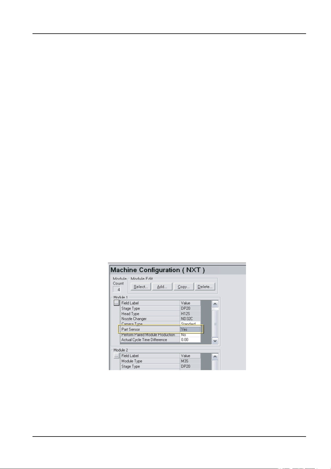
Specify module settings at the [Machine Configuration] section of Fuji Flexa.
1. Click the [Module] tab at the bottom of the Machine Configuration pane.
2. Locate the module that has the head with the part sensor from the list of modules.
3. Select [Yes] for the [Part Sensor] setting for the module.
4. Specify this setting for any other modules that have a head with a parts sensor.
01NST-0209E
3. Job Builder QD004-18
46 NXT Programming Manual
Settings in shape data
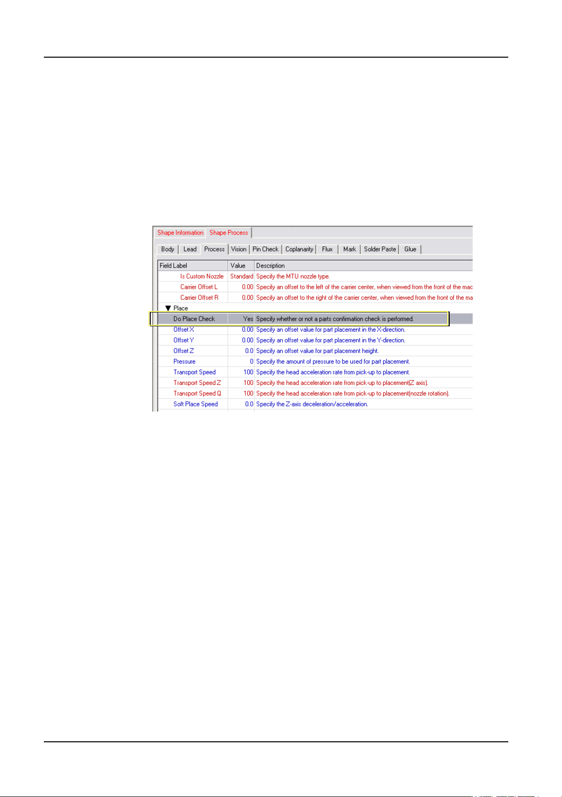
Specify that the presence of the part is to be checked by specifying the following setting in
the shape data (part data) for the part in Fuji Flexa.
1. Select the [Shape Data] tab from the job information bar in Job Builder.
2. Double-click the name of the shape data for the part. The shape data settings are
displayed.
3. Select the [Shape Process] tab and then select the [Process] tab.
4. Select [Yes] for the [Do Place Check].
01NST-0210E
QD004-18 3. Job Builder
NXT Programming Manual 47
3.4.6 Using the tray unit-LT and LTC
The tray unit-LT/LTC uses two magazines, allowing it to handle many parts for production
and perform part resupply during production. Four operation modes are available for use
depending on the production type. Use each type according to your needs.
Required items
See below for the supported software for each tray unit.
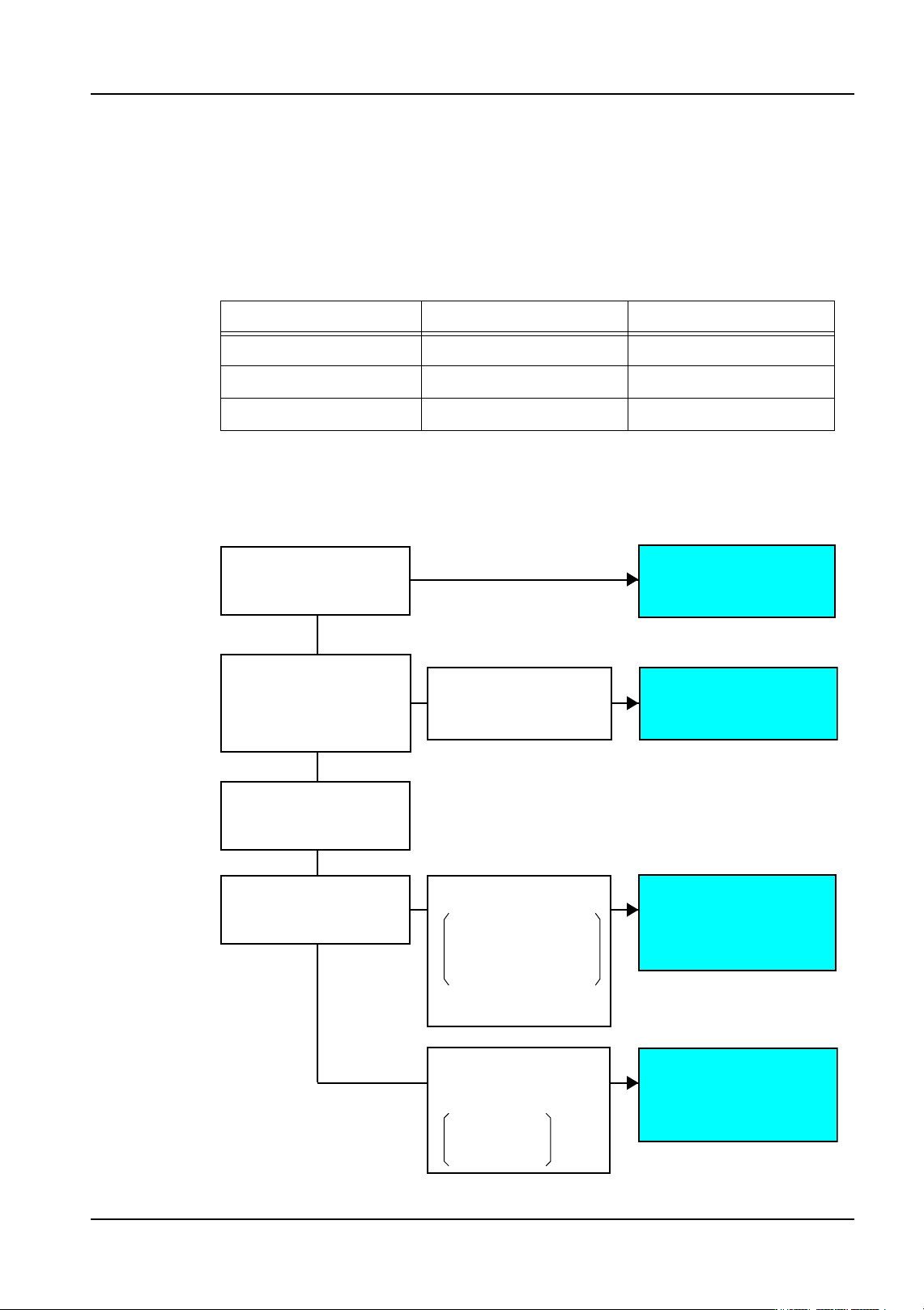
Operation mode selection
Select the operation mode that best suits the production type by referring to the following
chart.
Tray unit-LT Tray unit-LTC
NXT application software V5.03 V5.15
Fuji Flexa V4.2.0 V5.0.0 + Patch
Fujitrax V4.30 V5.01
Which is prioritized?
How many slots
are required for
production?
You want to reduce
changeover time because
changeover is performed
frequently
> More than 12 slots
You want to reduce downtime
during part resupply to improve
production efficiency
What is the supply
method?
* Reduce changeover time
* Improve production
efficiency
You do not want partially
used trays and want to
supply parts after they
have run out.
You don't care if partially
used trays occur.
[Mode 3]
[Mode 1]
[Mode 2]
[Mode 4]
Producing while reducing
changeover time
Producing panels with
many part types
Producing with minimum
downtime when resupplying
parts
Parts are required from
the resupply magazine
during production
01PRG-0118E
> Reduce changeover time
> Improve production efficiency
Usable slots
LT: 9 slots
LTC: 10 slots
You want to produce while
minimizing downtime.
Because there is only one
part type, you want to load
them on many trays to make
the time between resupply
as long as possible.