FUJI NXT Programming Manual QD004-18.pdf - 第113页
QD004-18 4. Part Data Settings NXT Programming Manual 103 4.5.2 P_patterns not supported by the NXT The following p_pa tterns are not valid for the NXT due to background conditions and/or th e use of backlightin g. P_ pa…
4. Part Data Settings QD004-18
102 NXT Programming Manual
4.5 P_pattern Details
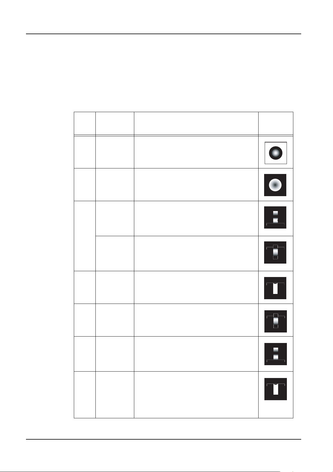
The p_pattern specifies the way the lead appears to the vision processing system and how
the processing of the lead information for the part is to be performed. In addition, it is
necessary to be aware that the placing position is affected by the specified p_pattern.
4.5.1 P_patterns used for the NXT
The following p_patterns are valid for use on the NXT with the frontlight system.
P_
patte
rn
Example
Part
Details Lead
Appearan
ce
1 Bump parts White body parts
2 Bump parts
Column
parts
Black body parts
4 SOIC Lead tip and width detection is performed.
The results are used for positioning
information. Lead length is not used for
positioning information with p_pattern types
12 and 14.
SOJ The lead ends do not display well, but lead
length is used for acquiring position
information. Lead length is not used for
acquiring positioning information with
p_pattern type 12.
6 LCC Leads point into the body and the lead tips
and width are detected. These results are
used for positioning information.
12 PLCC Because the lead ends do not display well,
lead width only is used for acquiring position
information. In some cases, processing is
more stable when using p_pattern type 14.
14 QFP Lead tip and width detection is performed.
Because the lead width direction positioning is
only required for determining the positioning,
only the lead width direction results are used
for positioning information.
16 LCC Leads extend into the body and the lead tips
and width are detected. These results are
used for positioning information. Because the
lead width direction positioning is only
required for determining the positioning, only
the lead width direction results are used for
positioning information.
QD004-18 4. Part Data Settings
NXT Programming Manual 103
4.5.2 P_patterns not supported by the NXT
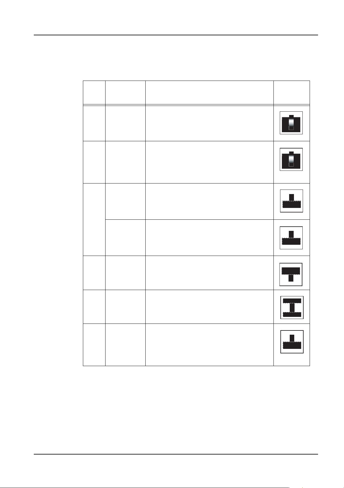
The following p_patterns are not valid for the NXT due to background conditions and/or the
use of backlighting.
P_
patte
rn
Example
Part
Details Lead
Appearan
ce
24 SOJ Used only with a white background. Lead tip
and width detection is performed. The results
are used for positioning information. Lead
length is not used for positioning information
with p_pattern type 34.
34 PLCC Used only with a white background. Lead tip
and width detection is performed. Because
the lead width direction positioning is only
required for determining the positioning, only
the lead width direction results are used for
positioning information.
3 SOIC Used only with backlighting. Lead tip and
width detection is performed. The results are
used for positioning information. Lead length
is not used for positioning information with
p_pattern types 11 and 13.
SOT Used only with backlighting. Lead tip and
width detection is performed. The results are
used for positioning information. Lead length
is not used for positioning information with
p_pattern types 11 and 13.
5 PLCC
Socket
Used only with backlighting. The leads point
towards the inside of the body. Lead tip and
width detection is performed. The results are
used for positioning information.
11 TAB Used only with backlighting. Because the
lead tip and base are both connected to the
body, only the lead width is use for positioning
information.
13 QFP Used only with backlighting. Lead tip and
width detection is performed. Because the
lead width direction positioning is only
required for determining the positioning, only
the lead width direction results are used for
positioning information.
4. Part Data Settings QD004-18
104 NXT Programming Manual
4.5.3 P_pattern explanations
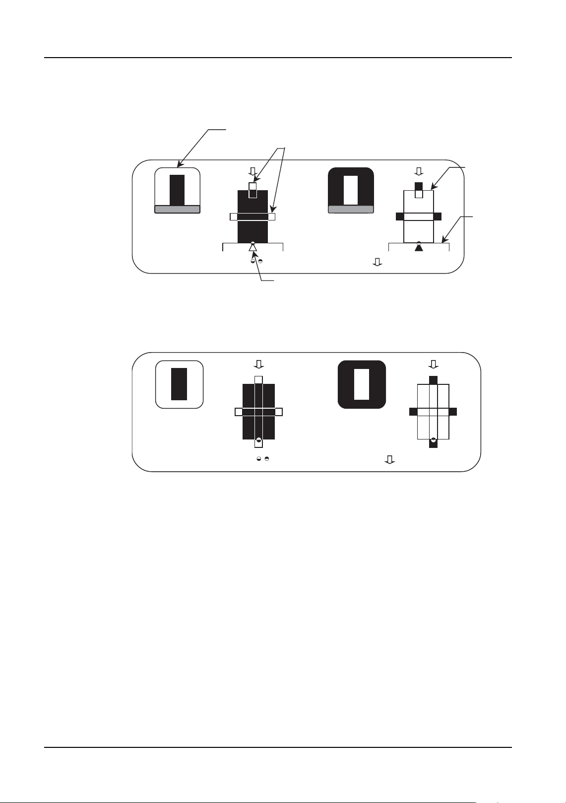
P_pattern diagram explanation
P_pattern 1, 2
Because the lead and body boundary is clearly defined, all four sides of the leads are
checked and the results are used to determine the part positioning.
• Type 1: The leads appear black and the outside circumference is white.
• Type 2: The leads appear white and the outside circumference is black
These are primarily used for parts with bumps.
Example Target Parts
Type 1: White body bumped parts processed with frontlighting.
Type 2: Black body bumped parts or CCGAs processed with frontlighting.
NXTVPP012E
P_pattern diagram displayed in the host system
Checked position caliper not used to determine positioning*1
Lead
Body
Checked position calipers used to determine positioning*1
:Entered element position
:Defined element direction
Type 7 Type 8
*1 The caliper is a vision processing tool used for detecting the boundary between light and dark.
NXTVPP013E
:Defined element direction
Type 1 Type 2
:Entered element position