FUJI NXT Programming Manual QD004-18.pdf - 第153页
QD004-18 4. Part Data Settings NXT Programming Manual 143 *1: There are cases in which none of the visi on types in the above table are applicable. Some examples of such parts are rectangular parts oth er than rectangula…
4. Part Data Settings QD004-18
142 NXT Programming Manual
Note: The p pattern is automatically converted if the old vision type is in the “generic” section.
Note: The shaded areas represent the vision types for which automatic conversion is not
supported by the NXT machines. All other vision types are supported and therefore require
no additional data entry.
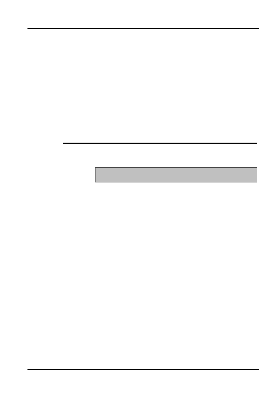
Note 1
Previously, it was possible to perform vision processing for all rectangular chips using vision
type 10, however, when using frontlighting, due to the influence of leads and so forth on the
body of the part, it is necessary to separate those parts previously supported by vision type
10 into four types as detailed in the table below.
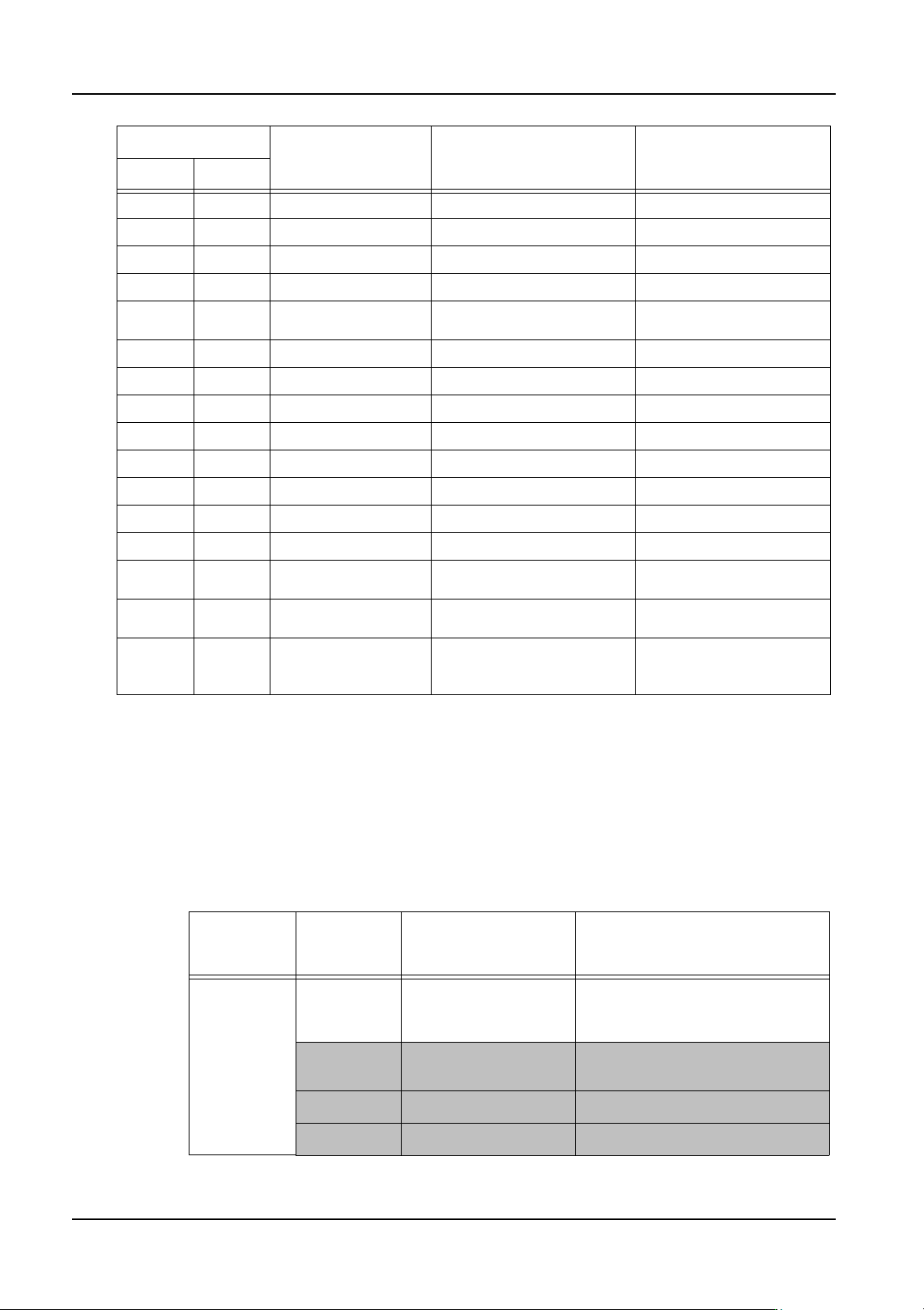
151 (156) 151 (156) Conversion not required Mechanical chuck connectors
152 (157) 152 (157) As above Black bodied connector
153 (158) 153 (158) As above White bodied connector
160 (165) 160 (165) As above White bodied connector detection
170 170 As above Mechanical chuck part presence
check
180 (185) 180 (185) Conversion not required Tantalum capacitors, SOTs
181 Coil parts 2 leads at 45 degrees angles
230 (235) 230 (235) Conversion not required Black BGA
231 (236) 231 (236) As above White BGAs
232 (237) 230 (235) As above TBGA
233 (238) 233 (238) As above Black CSPs
234 (239) 234 (239) As above White CSPs
240 240 VPDplus (MPA) NXT V3.0 and higher
249 252 Diagonal cut shield parts No longer used. Certain parts
supported by 252.
252 252 Multi-purpose vision type (part
outline)
254 252 Odd-form parts Select an appropriate vision type
based on part shape.
Override required (Note 5)
Vision Types New P Pattern Part Type Notes
Old NXT
Vision type
for existing
machines
Vision type
for NXT
Part type Explanation
10 60 Rectangular chips Automatically converted to 60 if
no vision type value is specified
in the NXT override section
65 Aluminum electrolytic
capacitors
Element data not required
180 Tantalum capacitors Element data reguired
(*1) Leaded parts Element data required
QD004-18 4. Part Data Settings
NXT Programming Manual 143
*1: There are cases in which none of the vision types in the above table are applicable.
Some examples of such parts are rectangular parts other than rectangular chips, tantalum
capacitors, or aluminum electrolytic capacitors with multiple leads inside the edge of the
part body. In this case, select an appropriate vision type from 123, 124, 144, or 180 and
enter element information for the leads based on the shape of the part.
Note: Vision type 10 is automatically converted to 60, however, if another value has been
specified in the override vision type value for the NXT, this value will be used.
Note: Refer to Åu4.6.2NXT vision typesÅv for details on how to create lead data.
Note 2
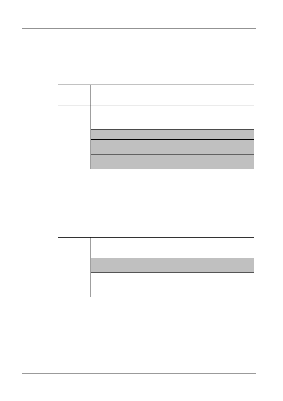
Vision type 20 is used on existing machines to process SOT-type parts with few leads,
however, on the NXT machines, vision type 180 is used. A custom vision type is used for
power transistors.
Note: Vision type 20 is automatically converted to 180, however, if another value has been
specified in the override vision type value for the NXT, this value will be used.
Vision type
for existing
machines
Vision type
for NXT
Part type Explanation
20 180 Tantalum capacitors,
SOTs
Automatically converted to 180 if
no vision type value has been
specified in the NXT override
section.
75 Power transistors P_pattern automatically
converted
4. Part Data Settings QD004-18
144 NXT Programming Manual
Note 3
Vision type 40 is used on existing machines to process parts with backlighting, using the
calculated body position as the placing reference point. The NXT machine, however, can
use either the body center or part center for the leaded (bumped) type parts. As a result,
there is no need to select a custom vision type. Select the appropriate vision type from the
following table based on the part type.
*2: Use the appropriate vision type (123, 124, 152, 153, or 180) depending on the leads and
the lead quantity.
Note: Vision type 40 is automatically converted to 160, however, if another value has been
specified in the override vision type value for the NXT, this value will be used.
Note 4
Vision type 150 is used on existing machines to process connectors with backlighting,
however, this vision type has now been separated as shown in the table below based on
body color.
Note: Vision type 150 is automatically converted to 153, however, if another value has been
specified in the override vision type value for the NXT, this value will be used.
Vision type
for existing
Machines
Vision type
for NXT
Part type Explanation
40 160 White bodied
connector detection
Automatically converted to 160 if
no vision type value has been
specified in the NXT override
section.
60 Rectangluar chips
252 Multi-purpose (part
outline)
(*2) Leaded parts P_pattern automatically
converted
Vision type
for existing
Machines
Vision type
for NXT
Part type Explanation
150
152 Black bodied
connectors
P_pattern automatically
converted.
153 White bodied
connectors
Automatically converted to 153 if
no vision type value has been
specified in the NXT override
section.